background image

      Performing Hardware Maintenance | 2

RADVISION | Maintenance Guide for SCOPIA Elite 5200 Series MCU Version 7.7

P/N 61546-00011


Replacing the MCU Chassis

The chassis of the MCU comprises the outer covering of the device, its single power supply, its 
two fan trays and its control blade. 

Before You Begin

To order a replacement chassis, contact your local RADVISION representative using the part 
number listed in this table.

Table 1-1

Ordering a replacement chassis for SCOPIA Elite 5200 Series MCU

Procedure

Step 1

Power off the MCU and disconnect it from the power outlet.

Step 2

Take the required antistatic precautions to avoid static electricity damages. This includes reading 
the Safety Guide for the SCOPIA Elite 5200 Series MCU and among other precautions wearing a 
wrist strap.

Step 3

Remove the grounding cable from the MCU chassis and disconnect all other connections.

Step 4

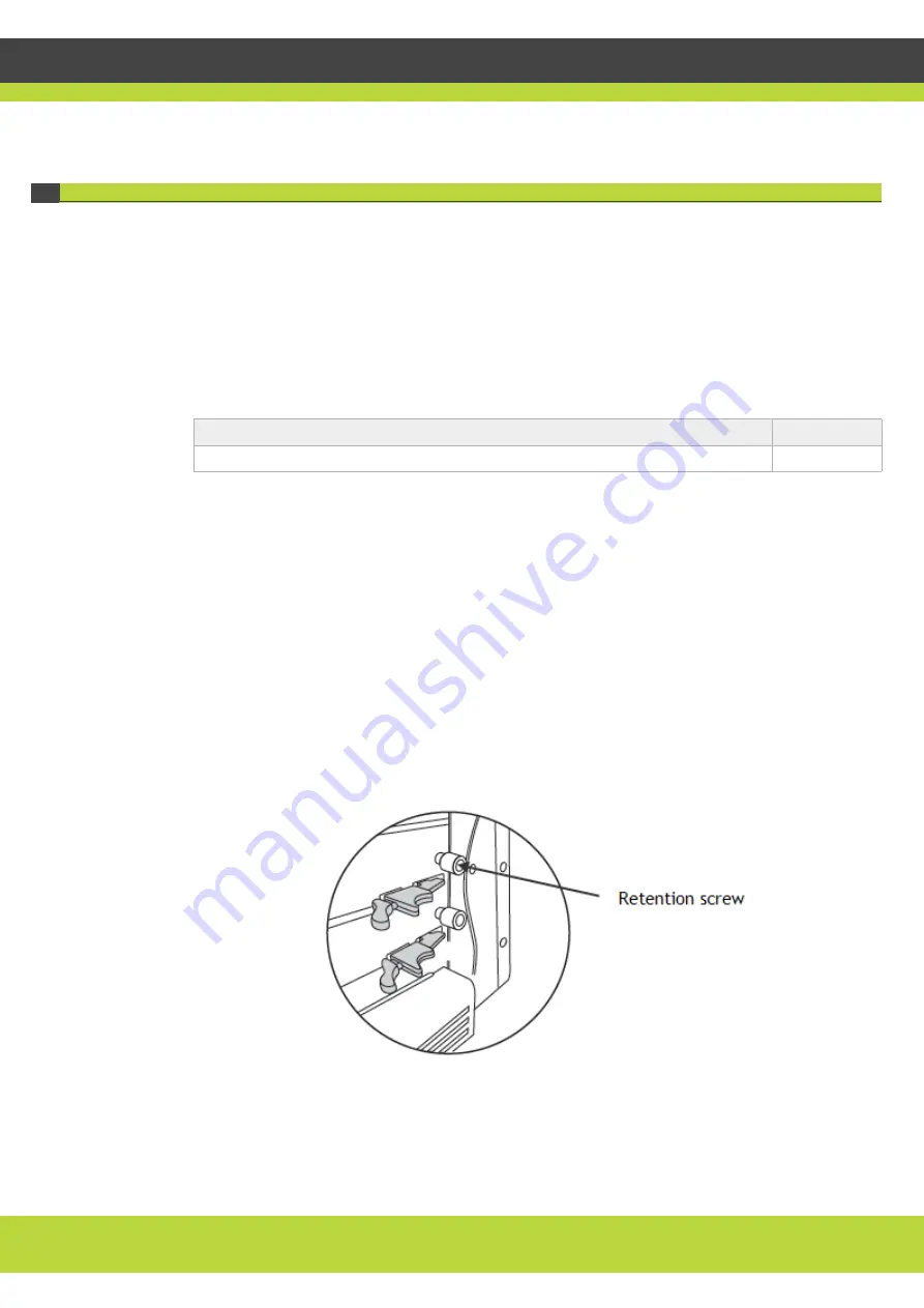
Release the retention screws of the lower media blade if it is installed in the model (see 

Figure 1-1 

on page 2

). Use a Phillips screwdriver if required. Repeat this step for the retention screws of the 

primary (upper) media blade.

Figure 1-1  

Releasing the retention screw

Name

Part number

SCOPIA Elite 5200 Series MCU Chassis

55546-00603

Содержание SCOPIA Elite 5200

Страница 1: ...SCOPIA Elite 5200 Series MCU Version 7 7 Maintenance Guide...

Страница 2: ...guide is made either by RADVISION Ltd or its agents RADVISION Ltd reserves the right to revise this publication and make changes without obligation to notify any person of such revisions or changes RA...

Страница 3: ...are Maintenance Replacing the MCU Chassis 2 Replacing the MCU Media Blade 3 Replacing the MCU Control Blade 5 Replacing the MCU Fan Drawer 5 Cleaning or Replacing the MCU Air Filter 8 Installing or Re...

Страница 4: ...ecautions Inspect the spare parts package for any damages and unpack taking into consideration the lifting guidelines detailed in the user guide Compare the package contents with the packing list and...

Страница 5: ...1 Power off the MCU and disconnect it from the power outlet Step 2 Take the required antistatic precautions to avoid static electricity damages This includes reading the Safety Guide for the SCOPIA E...

Страница 6: ...lade is aligned with the chassis panel Rotate the latch inward to secure the blade connections inside the chassis Repeat for the lower media blade Step 9 Tighten the retention screws Step 10 If requir...

Страница 7: ...Phillips screwdriver if required Step 5 Rotate the latch and slide the media blade out of its slot see Figure 1 2 on page 3 Step 6 Slide the replacement media blade into the slot until the outer pane...

Страница 8: ...p 4 Slide the replacement control blade into the chassis slot until the outer panel of the control blade is aligned with the chassis panel Rotate the latch inward to secure the blade connections insid...

Страница 9: ...ls A missing fan drawer is returned to the chassis Before You Begin To install or replace the fan drawer you need these parts and tools A grounding strap A replacement fan drawer To order contact your...

Страница 10: ...ntinue to rotate at high speed for several seconds To avoid injury you must hold the fan drawer by its handle until the fans stop rotating Step 3 Install the replacement fan drawer a Align the fan dra...

Страница 11: ...er without powering off the MCU only if you are able to do it within five minutes Otherwise we recommend that you power off the MCU before replacing the air filter Before You Begin Make sure you have...

Страница 12: ...it Hot water and mild detergent if the filter is too dirty to be completely cleaned with a vacuum or with plain water immerse the filter in a solution of hot water and mild detergent Rinse the filter...

Страница 13: ...f the MCU Step 3 Remove the PSU cover see Figure 1 7 on page 10 a Insert the slot head screwdriver into the opening on the left side of the PSU cover and gently push sideways Figure 1 7 Removing the P...

Страница 14: ...Figure 1 8 Locating the PSU compartment cover Step 5 Loosen the thumbscrew that secures the filling panel and remove the panel Step 6 Open the handle of the redundant PSU see Figure 1 9 on page 11 Ins...

Страница 15: ...wer inlet using the cross head screwdriver Step 11 Plug in the power cord of the redundant PSU Step 12 Turn on the redundant PSU switch from the rear panel Step 13 On the front panel check fan operati...

Страница 16: ...n You can import the settings of a saved MCU configuration file from a storage device on your network You can use the saved configuration file to restore the settings to the current MCU or to configur...

Страница 17: ...g systems innovative converged mobile services and highly scalable video enabled desktop platforms on IP 3G and emerging next generation IMS networks To gain additional insights into our products tech...

Отзывы: