© 2015 Radiodetection Ltd
27
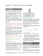
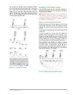
The line with the highest current measurement, rather
than the line giving the strongest response, is the target
line to which the transmitter signal has been connected.
Measuring current provides useful information about the
position of bends and intersections. Measuring current
after a tee will indicate the main line that pulls more
current along its greater length.
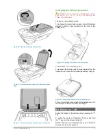
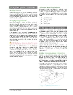
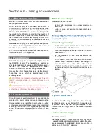
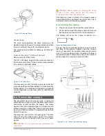
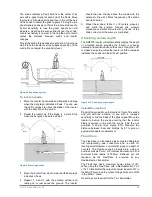
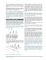
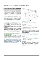
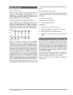
Figures 6.4
– 6.6 Taking current readings
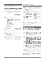
Applying a transmitter signal
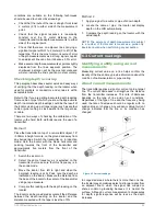
The transmitter signal can be connected, clamped or
induced to the target line in the same way as the signal
for line tracing is applied.
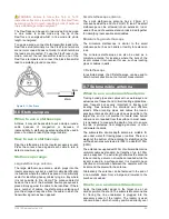
WARNING! Direct Connection to live conductors is
POTENTIALLY LETHAL. Direct Connections to live
conductors should be attempted by fully qualified
personnel only using the relevant products that allow
connections to energized lines.
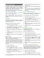
Signal current measurements
Pinpoint the line and confirm the accuracy of the Peak
pinpoint with null arrows. Check the locator is directly
over the line, with the antennas at right angles to it and
vertical.
The locator will automatically estimate and display depth
on the LCD.
A signal coupled to a nearby line may distort the
accuracy of the measurement. If the accuracy of the
reading is suspect, sweep the area to check if other
nearby lines are radiating the signal. If other signals are
causing interference, it may be necessary to make the
current measurement at another point along the line.
Both antennas are needed to make a current
measurement and locator accessory antennas such as
a normal clamp or stethoscope cannot be used.
Because current measurement is a function of depth, it
is only available in the locating modes. It is also available
with Current Direction (CD) clamps.
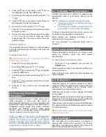
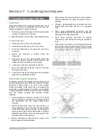
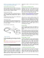
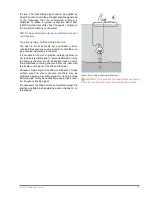
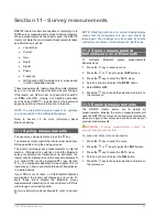
Figure 6.7: Current readings using transmitter signals

