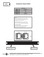
St Model HUB12
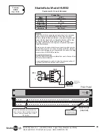
Engineered for St to Audio Science Audio Card Break-Out
General
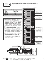
The Hub12 is specifically engineered to break-
out up to 8 stereo output channels and 4 stereo
input channels from series 4000, 5000 and
6000 Audio Science professional multi-channel
audio cards. Inputs and outputs appear on RJ-
45 connectors and conform to the St
audio pin-out standard. Front panel high-
density MD-50 & MD-26 connectors mate with
similar connectors on the various ASI cards
supported.,
BNC Synchronous connectors
Front panel BNC connectors provide Word-
Clock sync inputs and outputs as supported by
the individual ASI card models.
Insert internal jumpers JU-9 & JU-10 to activate
these connectors.
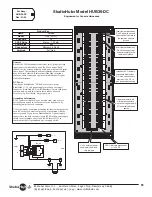
Grounding Information
Front panel RJ-45 shields are all normally
isolated from each other, but may be connected
together via a common ground bus by inserting
internal jumpers JU-1 thru JU-12. This bus may
be connected to the HUB12 chassis ground by
inserting internal jumper JU-15.
For Assys:
HUB12
Rev: 01/05
Name
HUB12
Mount
rack (1 r.u.)
Channels
8 Out / 4 In
CAT-5 Pairs
2 (all)
Power Link
no
Connectors
12 RJ-45 / 2 BNC (for sync.)
1 MD-50 (for analog) / 1 MD-26 (for digital)
Versions
Rack-mount only (as pictured)
Product Key
Analog I/O
Connector (MD-50)
8
7
6
5
4
3
2
1
RJ-45
Chassis
Ground
50 Pin
Miniature D
Analog I/O
26 Pin
Miniature D
Digital I/O
Common
Ground
World Clock In
World Clock Out
JU1
JU15
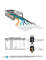
St Pin Outs
Channel
Color Pair
RJ-45 Pin
110 Pin
L+ / AES +
Wht/Org
1
3
L- / AES -
Org/Wht
2
4
R+
Wht/Grn
3
5
R-
Grn/Wht
66
nc
Wht/Blu
5
1
GND
Blu/Wht
4
2
15V-
Wht/Brn
7
7
15V+
Brn/Wht
8
8
Shield
Wht/Slt
Shield
9
Shield
Slt/Wht
Shield
10
NOTE - These pin-outs typically correlate 1 to 1 for Audio
Science series 4000, 5000 and 6000 audio cards so that straight-
thru patch cables may be utilized.
Digital I/O
Connector (MD-26)
INPUT 1
LEFT -
1
INPUT 1
RIGHT -
2
INPUT 2
LEFT -
3
INPUT 2
RIGHT -
4
INPUT 3
LEFT -
5
INPUT 3
RIGHT -
6
INPUT 4
LEFT -
7
INPUT 4
RIGHT -
8
OUTPUT 4 RIGHT -
9
OUTPUT 4 LEFT -
10
OUTPUT 3 RIGHT -
11
OUTPUT 3 LEFT -
12
OUTPUT 2 RIGHT -
13
OUTPUT 2 LEFT -
14
OUTPUT 1 RIGHT -
15
OUTPUT 1 LEFT -
16
OUTPUT 5 RIGHT -
17
OUTPUT 5 LEFT -
18
OUTPUT 6 RIGHT -
19
OUTPUT 6 LEFT -
20
OUTPUT 7 RIGHT -
21
OUTPUT 7 LEFT -
22
OUTPUT 8 RIGHT -
23
OUTPUT 8 LEFT -
24
GROUND
25
26
INPUT 1
LEFT +
27
INPUT 1
RIGHT +
28
INPUT 2
LEFT +
29
INPUT 2
RIGHT +
30
INPUT 3
LEFT +
31
INPUT 3
RIGHT +
32
INPUT 4
LEFT +
33
INPUT 4
RIGHT +
34
OUTPUT
RIGHT +
35
OUTPUT
LEFT +
36
OUTPUT
RIGHT +
37
OUTPUT
LEFT +
38
OUTPUT
RIGHT +
39
OUTPUT
LEFT +
40
OUTPUT
RIGHT +
41
OUTPUT
LEFT +
42
OUTPUT
RIGHT +
43
OUTPUT
LEFT +
44
OUTPUT
RIGHT +
45
OUTPUT
LEFT +
46
OUTPUT
RIGHT +
47
OUTPUT
LEFT +
48
OUTPUT
RIGHT +
49
OUTPUT
LEFT +
50
GROUND
14
INPUT 1 AES +
15
INPUT 2 AES +
16
INPUT 3 AES +
17
INPUT 4 AES +
18
OUTPUT 1 AES +
19
OUTPUT 2 AES +
20
OUTPUT 3 AES +
21
OUTPUT 4 AES +
22
OUTPUT 5 AES +
23
OUTPUT 6 AES +
24
Sync
25
Word Clock
26
GROUND
INPUT 1 AES-
1
INPUT 2 AES-
2
INPUT 3 AES-
3
INPUT 4 AES-
4
OUTPUT 1 AES-
5
OUTPUT 2 AES-
6
OUTPUT 3 AES-
7
OUTPUT 4 AES-
8
OUTPUT 5 AES-
9
OUTPUT 6 AES- 10
Sync
11
Word Clock
12
GROUND
13
Radio Systems, Inc.
•
601 Heron Drive
•
Logan Twp., New Jersey 08085
(856) 467-8000
•
Fax (856) 467-3044
•
www.studiohub.com
7
Содержание DA12-DC
Страница 1: ...Technical Manual for Hubs Updated 09 07 ...


