Radio Systems, Inc.
•
601 Heron Drive
•
Logan Twp., New Jersey 08085
(856) 467-8000
•
Fax (856) 467-3044
•
www.studiohub.com
9
St GPI 12/24 Channel
Remote Control Hub
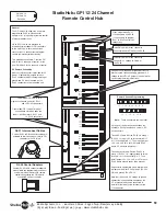
RJ-21 Interconnect Cables
Custom RJ-21 to DB connector cables are
available to interconnect every major GPI
controller to the GPI Hub
General
The GPI Hub-12/24 allows the use of pre-
programmed RJ-45 to DB connector
adapters, for
plug and play remote control
of many broadcast units.
DB to RJ-21 cables are provided to
interconnect most popular GPI controllers
to the Hub-12/24, where the user than
crosscut the 110 connectors to program
various remote control functionality.
Two models are available. Order the GPI
Hub-12 for 12 channels of control, or the
dual GPI Hub-24 for 24 channels of control.
DC Power & Grounding
A barrier strip connector is provided for DC
power. Programming jumpers for each
RJ-45 channel allow quick programming of
ground and DC when required on the
RJ-45 connection to the controlled unit.
GPI Hub-12
GPI Hub-24
Rev.05/06
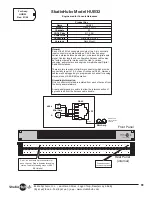
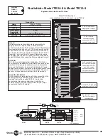
Order model GPI Hub-12 for a
single circuit board unit with 1 RJ-21
and 12 RJ-45 connectors.
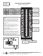
Order model GPI Hub-24 for a dual
circuit board unit which adds the
lower circuit board for 2 RJ-21 and
24 RJ-45 connectors.
Install this jumper at any channel to
connect ground to Pin #5 of the RJ-45
Install this jumper at any channel to
connect DC + voltage to Pin #8 of
the RJ-45
JU1
JU2
JU3
JU4
JU5
JU6
JU7
JU9
JU10
JU11
JU12
JU13
JU14
JU15
JU16
JU17
JU18
JU19
JU20
JU21
JU22
JU23
JU24
JU8
JU1
JU2
JU3
JU4
JU5
JU6
JU7
JU9
JU10
JU11
JU12
JU13
JU14
JU15
JU16
JU17
JU18
JU19
JU20
JU22
JU23
JU24
JU8
Cross-cut between RJ-21
110 connectors and RJ-45
110 connectors to program
RJ-21 to RJ-45 control line
connectivity
JU21
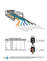
RJ-45 Control Adapters
Custom RJ-45 to DB connector adapters
are available pre-programmed to connect
every major manufacturers DB remote
control connector to the GPI hub via
standard RJ-45 patch cables
Power & Ground Programming
Note:
These connecters are in parallel
3 groups of + and ground connections are
available. Each group feeds 3 sets of 4 RJ-
45 connectors.
To send DC to pin 8 of the RJ-45's in group 1
(RJ-45's 1-4), apply DC to screw te1
or 110 connector pin +1. Then install jumper
JU2, JU4, JU5, JU6, or JU8 at each RJ-45
where DC needs to be present.
To send ground to pin 5 of the RJ-45's in
group 1 (RJ-45's 1-4), apply ground to screw
terminal -1 or 110 connector pin -1. Then,
install jumper JU1, JU3, JU5, or JU7 at each
RJ-45 where ground needs to be present.
Repeat (with appropriate screw terminal and
jumper numbers) for RJ-45 group 2 (RJ-45's
5-8) and group 3 (RJ-45 9-12)
Note that if the same DC voltage or ground
connection is needed between groups, the
DC or ground lead can be connected in
parallel at the lower screw terminals or the
110 connector.
Connect DC voltage and/or ground at this 110
block or screw terminal to apply ground or DC
voltage to these RJ-45 jumpers. (See below for
specific programming instructions).
+1 -1 +2 -2 +3 -3 S S
+1 -1 +2 -2 +3 -3
Содержание DA12-DC
Страница 1: ...Technical Manual for Hubs Updated 09 07 ...


