Radio Systems, Inc.
•
601 Heron Drive
•
Logan Twp., New Jersey 08085
(856) 467-8000
•
Fax (856) 467-3044
•
www.studiohub.com
For Assy:
PATCH-44
Rev: 01/05
St Model PATCH-44
with Front Panel Normalizing Switching
1
2
3
4
5
6
89
10
11
12
13
14
15
16
17
18
19
20
21
22
23
7
24
25
26
27
2829
30
31
32
33
34
35
36
37
3839
40
41
42
43
44
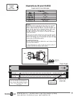
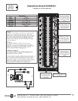
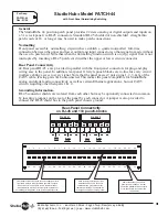
Front Panel normalizing switch connects upper jack left &
right audio inputs to lower jack left & right audio outputs
when switch is in up position. Audio remains present
(monitorable) on both input & output jacks regardless of
normalizing switch position or the insertion of patch cords.
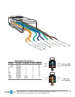
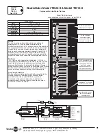
Each RJ-45 jack provides a stereo
balanced audio circuit. Jacks are
shielded, with a ground connection
that may be floated or commoned via
a rear panel jumper to chassis ground.
Audio connection to each front
panel jack is provided on the rear
panel via a parallel RJ-45 connector
or 110 punch style connection (see
chart below)
wht
/
blu
blu
/
wht
wht
/
org
org
/
wht
wht
/
grn
wht
/
blu
blu
/
wht
wht
/
org
org
/
wht
wht
/
grn
1
2
3
4
5
6
7
8
9
10
Left
Audio
Right
Audio
Left
Audio
Right
Audio
+
-
+
-
G
+
-
+
-
G
RJ-45 #1
RJ-45 #2
General
The St 44 position patch panel provides 22 stereo analog or digital outputs and inputs on
a 3 r.u. rack panel via RJ-45 connectors. Standard RJ-45 shielded or non-shielded straight-thru
patch cords of 18 or longer may be used to make patch connections.
Normalling
Front panel accessible normalling dip-switches establish a quarter normalled full-time
connection between the upper and lower output and input connectors so that signal in made without
the use of a patch-cord. Note that when the normalling function switch is on (up,) signal flow is not
interrupted by inserting a RJ-45 patch cord in either the upper or lower circuit connector.
Rear Panel Connectivity
44 Rear panel RJ-45 s are provided in parallel with the front panel connectors for plug-and-play
wiring ease to the panel. In addition, rear panel 110-style punch blocks are in-line for every circuit
to allow cabling access to every signal. Note that the panel passes 2 pairs (pins 1, 2, 3, &6) of the
CAT-5 cable, leaving pairs 3&4 unconnected. This makes the panel compatible for St
analog and digital audio connectivity as well as certain Ethernet applications, but not CAT-5
circuits requiring other then pairs 1 & 2.
Grounding Information.
RJ-45 connector shields are isolated from each other but may be optionally connected in common
by inserting a jumper on the rear of the panel by each connector. A jumper is also provided to
connect the RJ-45 shield bus to the patch panel chassis ground.
Rear-Panel Connectivity
on RJ-45 and 110 punch-blocks
bo
Содержание DA12-DC
Страница 1: ...Technical Manual for Hubs Updated 09 07 ...


