Stylus overhang adjustment
.
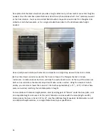
Traditional cartridges have the stylus located wholly under the cartridge body. Some recent cartridges
have a cantilever/stylus that is naked, extending beyond the front of the cartridge body. To handle both
architectures, the cartridge mounting pad has five pairs of drilled and tapped holes. These holes are
precisely drilled on a CNC mill, and are guaranteed to be perfectly parallel to each other and aligned to
the imaginary line emanating from the center spindle.
Cartridges vary in distance from the stylus to the cartridge mounting holes. To address this non-
standardization, there are five pairs of holes in the cartridge mounting pad. Some experimentation is
standardization, there are five pairs of holes in the cartridge mounting pad. Some experimentation is
needed to select the pair of holes that best accommodates both the stylus placement within the
cartridge, and the need to bisect the parallel line on the stylus alignment protractor.
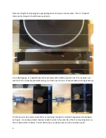
Aesthetically, the cartridge mounting pad looks best when its front edge is close to the front edge of the
wand. Turn the wand upside down and place the cartridge on it. Select the pair of holes where either
the naked stylus or the front of the cartridge is nearest to the front edge of the mounting pad. You may
prefer that the cartridge extends somewhat beyond the wand front, or be recessed inside the wand
front. However, too much extension, or too much recess is a sign that the neighboring pair of holes may
be a better choice.
Select a pair of black nylon screws from the accessories box, and the straight edge razor blade. (a sharp
Xacto knife or sharp shipping carton knife work as well.). Insert the two black nylon screws thru the
cartridge mounting holes and hand-tighten both screws as much as possible onto the cartridge
cartridge mounting holes and hand-tighten both screws as much as possible onto the cartridge
mounting pad. Tighten securely with a small Philips head screwdriver. Turn the cartridge and mounting
pad on its side, and cut off the excess nylon screw threads flush to the top of the cartridge mounting
pad.
Slide the cartridge/cartridge mounting pad into the front of the wand. You will note that the slide and
fit is snug, needing a modicum force to move. Delrin has a self-lubricating property. At close tolerances
between two Delrin parts, when the sliding stops, a tiny amount of “grab” takes over. Try to slide the
cartridge mounting pad slightly further into the wand than you want the final position to be. No signal
wires need be fitted at this time, as the cartridge may be pulled for another iteration.
Iterations:
The tone arm base plate’s position (right to left) on the turntable tone arm mounting board can now be
“finalized” thru iteration. We will be sliding the cartridge mounting pad, to set the stylus overhang.
11
“finalized” thru iteration. We will be sliding the cartridge mounting pad, to set the stylus overhang.
Exact overhang position is determined with a cartridge in the wand, and cuing it down onto the scribe
line. The goal is to have the stylus land in the center of the scribe line in two places, typically near first
band and last band on an LP.
Large iterations
: Up until now, we made “large” moves. We were either moving the entire arm on its
base to the right or left; or, selecting a different pair of cartridge mounting holes. We can assume that
those choices are “golden”, and so now move on to small iterations.


