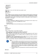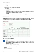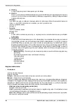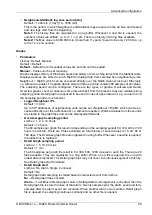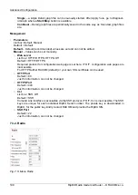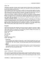
Default = Default
Default
– Default (recommended) values are set and can not be edited.
Manual
– Thresholds can be set manually. However there are individual min. and max. threshold
values for each item. When your settings are out of the possible interval, the web interface will give
you a warning and display the possible values.
•
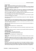
SNMP Trap
When ticked, the SNMP trap message is sent both when a parameter value exceeds the alarm
threshold and when it returns back within its “normal” range. Remember to set the IP destination
address(es) and port(s) for SNMP trap messages in Settings/Device/SNMP.
When even one SNMP trap tick box is reconfigured in Alarm table, all SNMP traps for active alarms
(out of thresholds) are re-sent with exception of the HW alarm input.
After reboot all SNMP traps for active alarms (out of thresholds) are re-sent, HW alarm input (HS
active when Hot standby is “On”) included.
When Statistic and Neighbours logs are cleared, RSScom, DQcom, ETH, COM1, COM2 alarms
are cleared as well.
When Hot Standby is “On”, Alarm thresholds and HW alarm input are used internally for switching
between units “A” and “B”. The “HW alarm input” parameter is changed to “Hot Standby active”.
Also HW alarm output for Temperature is always On. Its thresholds can be Manually set in interval
-50 to +90 °C (default -25 to +85 °C).
SNMP Alarm and Detailed Graphs tick boxes can be used for information about switching between
units “A” and “B”.
•
HW Alarm Output
List box: Off, N.O. (Normally Open), N.C. (Normally Closed)
Default = Off
If "
N.O.
" or "
N.C.
", the HW Alarm Output is active and its normal status (no alarm) is open or closed,
respectively.
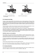
The HW Alarm Output is a pin (open n-p-n collector) on the screw terminal at the Power and Control
connector on the front panel.
•
Detail Graph start
It has to be activated in Settings/Device/Graphs first.
You can tick here for which Alarm Detail Graph will be saved.
•
HW Alarm Input
List box: Off, N.O. (Normally Open), N.C. (Normally Closed)
Default = Off
If "
N.O.
" or "
N.C.
", the HW Alarm Input is active and its normal status (no alarm) is open or closed,
respectively.
Alarm event is triggered when the HW Alarm Input changes its status from “Normal” to “Alarm”.
Note that to “Close” the HW Alarm Input means connecting the respective screw terminal at the
Power and Control connector on the front panel to the Ground terminal of the same connector.
•
HW Alarm Input
List box: Off, On
Default = Off
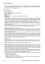
When “
On
”, the Hardware Alarm Output indicates the full functionality of the RipEX. The Hardware
Alarm Output is down only when the RipEX is not powered or it is booting. When SNMP Trap and/or
Detail Graphs are ticked in the Unit ready line, the respective action is taken after every Hardware
Alarm Output state change (and also when the Apply button is activated after a reconfiguration).
95
© RACOM s.r.o. – RipEX Radio modem & Router
Advanced Configuration
Содержание RipEX 1.6.0
Страница 2: ......

