1260-X133 User Manual
Installation Instructions 2-2
Racal Instruments
©
2005
Installation
Installation of the 1260-X133 Switching Module into a 1260-100X
Adapt-a-Switch Carrier assembly is described in the “Installation”
section of the 1260-100X Adapt-a-Switch Carrier manual.
For installation of the 1260-X133 into a 1256 Switching System,
refer to the 1256 User Manual.
Module
Configuration
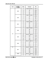
The 1260-X133 contains 20 configurable 1x4 multiplexers, 6 1x2
multiplexers and 6 configurable 1x2 multiplexers. On-board
configuration relays allow four 1x4 multiplexers to be configured in
to a 2x8 matrix, two 1x2 multiplexers to be configured into a 1x4
multiplexer.
Twenty 1x4 multiplexers are numbered from 0 through 19. Each
multiplexer (mux) is made up of four relays, referred to as
channels.
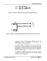
Figure 2-1
shows an example of one of these
multiplexers (multiplexer 5). In this example, the inputs are
channels 50 through 53. The user may close one or more relays to
connect the inputs to the common output.
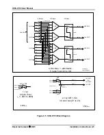
Five 2x8 matrix cells are named from X1 to X5, and numbered
from 0 to 4. Each matrix cell contains four 1x4 multiplexers which
are named from 4M1 to 4M3. Beside the 1x4 muxes, each cell also
contains 8 input configuration relays and two output configuration
relays which are number from 8x0 to 8x9 (x is from 0 to 4) as the
channels, 8x0 to 8x7 are inputs channels, 8x8 and 8x9 are outputs.
Figure 2-2
shows an example of one of 2x8 matrix cells (X3).
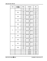
Six 1x2 multiplexers are named as Y cell, and numbered from 0
through 5 with 200 offset. Each multiplexer (mux) is made up of
two relays, referred to as channels.
Figure 2-3
shows an example
of one of these multiplexers (multiplexer 5). In this example, the
inputs are channels 250 through 251. The user may close one or
both relays to connect the inputs to the common output.
Six configurable 1x2 multiplexers are numbered from 0 through 5
with 400 offset. Each 1x2 multiplexer (mux) is made up of two
relays, referred to as channels. Three 1x4 mux can be configured
from these six 1x2 mux and three output configuration relays. They
are named from Z1 to Z3. The output configuration relays for three
1x4 muxs are numbered 501, 503 and 505 as channels.
Figure 2-
4
shows an example of one of these 1x4 multiplexers (multiplexer
2&3). In this example, the inputs are channels 420 through 421
and 430 through 431. The user may close one or more relays to
connect the inputs to the common output.
Содержание 1260-X133
Страница 8: ...1260 X133 User Manual iv This page was left intentionally blank...
Страница 14: ...1260 X133 User Manual Specifications 1 6 Racal Instruments 2005 This page was left intentionally blank...
Страница 36: ...1260 X133 User Manual Module Operation 3 10 Racal Instruments 2005 This page was left intentionally blank...


