background image

1260-X133 User Manual 

Racal Instruments 

©

 2005 


Product Support 4-1 

Chapter 4


PRODUCT SUPPORT 

Product Support 

Racal Instruments has a complete Service and Parts Department. 
If you need technical assistance or should it be necessary to return 
your product for repair or calibration, call 1-800-722-3262. If parts 
are required to repair the product at your facility, call 
1-949-859-8999 and ask for the Parts Department. 

When sending your instrument in for repair, complete the form in 
the back of this manual. 

For worldwide support and the office closes to your facility, refer to 
the Support Offices section on the following page. 


Reshipment 
Instructions


Use the original packing material when returning the 1260-X133 to 
Racal Instruments for calibration or servicing. The original shipping 
container and associated packaging material will provide the 
necessary protection for safe reshipment. 

If the original packing material is unavailable, contact Racal 
Instruments Customer Service for information. 

Содержание 1260-X133

Страница 1: ...imborne Dorset BH21 7PF United Kingdom Tel 44 0 1202 872800 Fax 44 0 1202 870810 Via Milazzo 25 20092 Cinisello B Milan Italy Tel 39 0 2 6123 901 Fax 39 0 2 6129 3606 Racal Instruments Group Limited T...

Страница 2: ...ent or misuse of any product or part The warranty also does not apply to fuses software non rechargeable batteries damage from battery leakage or problems arising from normal wear such as mechanical r...

Страница 3: ...ce purposes or for purposes of engineering evaluation and incorporation into technical specifications and other documents which specify procurement of products from Racal Instruments DISCLAIMER Buyer...

Страница 4: ...ion cord or a three prong two prong adapter This will defeat the protective feature of the third conductor in the power cord Maintenance and calibration procedures sometimes call for operation of the...

Страница 5: ...2 2 1 INSTALLATION INSTRUCTIONS 2 1 Unpacking and Inspection 2 1 Reshipment Instructions 2 1 Installation 2 2 Module Configuration 2 2 Connector Pin Assignments 2 6 Front Panel Connector 2 10 Mating...

Страница 6: ...Reply To The MOD LIST Command 3 5 Operating The 1260 X133 in Register Based Mode 3 5 Configuring Larger Multiplexers 3 8 Chapter 4 4 1 PRODUCT SUPPORT 4 1 Product Support 4 1 Reshipment Instructions...

Страница 7: ...able Multiplexer Example Channels 420 through 431 2 4 Figure 2 5 1260 X133 Block Diagram 2 5 Figure 2 6 Front Panel Connector Pin Numbering 2 11 Figure 3 1 Front View Module Addresses for 1 through 6...

Страница 8: ...1260 X133 User Manual iv This page was left intentionally blank...

Страница 9: ...0 100X Adapt a Switch Platform The 1260 X133 includes the following features Standard Adapt a Switch plug in design providing for ease of replacement Data driven embedded descriptor allowing immediate...

Страница 10: ...llution Class 2 DC 220 V Max Pollution Class 2 AC DC 300V Pollution Class 1 Switching Current AC 2 A Max DC 2 A Max Switching Power AC 62 5 VA Max DC 60 W Max Path resistance 1mA 700 m 1A 1 Capacitanc...

Страница 11: ...requires de rating of maximum overall power dissipation to 49W Power Dissipation While the cooling of the Adapt a Switch carrier is dependent upon the chassis into which it is installed the carrier c...

Страница 12: ...ug in should be no more than 15 W if all six slots are used simultaneously This yields the following guideline 0 5 A Max 71 channels closed 1 A Max 17 channels closed 2 A Max 4 channels closed The num...

Страница 13: ...10346 The relay manufacturer s specifications for this relay are Life Expectancy Mechanical 100 000 000 operations Electrical 100 000 operations at full rated load 500 000 operations at 30VDC 1A resis...

Страница 14: ...1260 X133 User Manual Specifications 1 6 Racal Instruments 2005 This page was left intentionally blank...

Страница 15: ...the carrier if any damage is apparent 4 Have a qualified person check the instrument for safety before use CAUTION The instrument contains ESD sensitive devices Open the package at an ESD safe work s...

Страница 16: ...plexers which are named from 4M1 to 4M3 Beside the 1x4 muxes each cell also contains 8 input configuration relays and two output configuration relays which are number from 8x0 to 8x9 x is from 0 to 4...

Страница 17: ...4M3 4M4 Ta Ta Ta Ta Ta Ta Ta Ta Tb Tb Tb Tb Tb Tb Tb 1x4 IN 1x4 IN 1x4 IN 1x4 IN Tb 2x8 ROW 2X8 COL 1x4 OUT 7 5 6 3 2 4 7 5 6 3 2 4 IN1 IN2 IN3 IN4 IN1 IN2 IN3 IN4 IN1 IN2 IN3 IN4 IN1 IN2 IN3 IN4 8 Re...

Страница 18: ...usly connect any combination of mux inputs to the common output of the same multiplexer For example referring to Figure 2 1 the user may connect the channel 51 and channel 53 inputs to the common outp...

Страница 19: ...IN4 8 Relays 16 Relays 2 Relays 130 Relays 100 I O Signals 15 Relays 18 I O Signals 2X8 COL 1x4 OUT 7 5 6 3 2 4 2 1x2 OR 1 1X4 3 Cells Total Z1 to Z3 2M1 2M2 1x2 OUT OR 1x4 OUT 1x2 OUT 3 2 4 12 Relays...

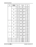
Страница 20: ...onnections for J200 Cell 1x4 MUX 1X2 MUX Mux Channel Pin 0 Mux 0 Common A19 0 0 A32 0 1 A29 0 2 A26 4M1 0 3 A23 1 Mux 1 Common A16 1 10 A12 1 11 A9 1 12 A6 4M2 1 13 A3 2 Mux 2 Common A17 2 20 A30 2 21...

Страница 21: ...B10 7 71 B7 7 72 B4 4M4 7 73 B1 8 Mux 8 Common C19 8 80 C32 8 81 C29 8 82 C26 4M1 8 83 C23 9 Mux 9 Common C16 9 90 C12 9 91 C9 9 92 C6 4M2 9 93 C3 10 Mux 10 Common C17 10 100 C30 10 101 C27 10 102 C2...

Страница 22: ...ux 15 Common D14 15 150 D10 15 151 D7 15 152 D4 4M4 15 153 D1 16 Mux 16 Common E19 16 160 E32 16 161 E29 16 162 E26 4M1 16 163 E23 17 Mux 17 Common E16 17 170 E12 17 171 E9 17 172 E6 4M2 17 173 E3 18...

Страница 23: ...0 Mux 24 Common C5 24 240 D8 2M5 24 241 D2 250 Mux 25 Common B5 25 250 A8 2M6 25 251 A2 400 Mux 40 Common D28 40 400 E31 2M1 40 401 E25 410 Mux 41 Common E20 41 410 D22 Z1 2M2 41 411 D18 420 Mux 42 Co...

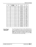
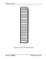
Страница 24: ...2 Ground E18 Ground E13 Ground E8 Ground E2 Front Panel Connector The 1260 X133 has one front panel connector labeled J200 It is a 160 pin modified DIN style connector with 0 025 square posts as pins...

Страница 25: ...User Manual Racal Instruments 2005 Installation Instructions 2 11 Figure 2 6 Front Panel Connector Pin Numbering a b c d e 31 30 29 28 27 26 25 24 23 22 21 19 18 17 16 15 14 13 12 11 10 9 8 7 6 5 4 3...

Страница 26: ...ing connector for the 1260 X133 The other end is unterminated Refer to Table 2 1 for channel to pin mapping information P N 407664 160 Pin Connector Kit with Pins This kit provides the mating connecto...

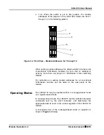
Страница 27: ...odule address assigned to the 1260 X133 is determined by the carrier slot into which the 1260 X133 is inserted and by the position of the logical address DIP switch on the carrier side panel The logic...

Страница 28: ...used by more than one plug in or 1260 Series C Size switching module For instructions on setting module addresses for a conventional 1260 Series module see the label on the side panel of the module O...

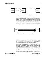
Страница 29: ...g the register based mode it is advisable to use either the message based or the register based mode and continue to use the same mode throughout the application program In general the message based m...

Страница 30: ...elay command uses a channel descriptor to select the channel s of interest The syntax for a channel descriptor is the same for all 1260 series modules In general the following syntax is used to select...

Страница 31: ...In register based mode the 1260 X133 is operated by directly writing and reading control registers on the 1260 X133 module When a control register is written to all channels controlled by that regist...

Страница 32: ...d conventional 1260 Series modules are always on odd numbered A24 addresses The three control registers for the 1260 X133 reside at the first three odd numbered A24 addresses for the module Base A24 A...

Страница 33: ...3 16 849 848 190 844 170 150 834 130 17 Unused Unused 191 845 171 151 835 131 18 Unused Unused 192 846 172 152 836 132 19 Unused Unused 193 847 173 153 837 133 20 Unused Unused 221 220 211 210 201 200...

Страница 34: ...sed to control the module The VISA function viOut8 is used to write a single 8 bit byte to a control register while viIn8 is used to read a single 8 bit byte from the control register The following co...

Страница 35: ...2 2 close CH111 in MUX11 From table 3 1 we can see that the CH825 is controlled by bit 4 of control register 10 and CH 829 is controlled by bit 7 of control register 9 The Bit 4 of control register 1...

Страница 36: ...1260 X133 User Manual Module Operation 3 10 Racal Instruments 2005 This page was left intentionally blank...

Страница 37: ...Parts Department When sending your instrument in for repair complete the form in the back of this manual For worldwide support and the office closes to your facility refer to the Support Offices sect...

Страница 38: ...78249 Tel 210 699 6799 Fax 210 699 8857 Europe European Headquarters and Service Center 18 Avenue Dutartre 78150 LeChesnay France Tel 33 0 1 39 23 22 22 Fax 33 0 1 39 23 22 25 29 31 Cobham Road Wimbo...

Страница 39: ...e Zip Postal Code Country Technical Contact Phone Number Purchasing Contact Phone Number 1 Describe in detail the problem and symptoms you are having Please include all set up details such as input ou...

Отзывы: