User’s Manual
3
1.2 Development and Evaluation Tools
1.2.1 Tool Kit
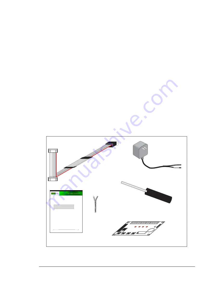
A Tool Kit contains the hardware essentials you will need to use your OP7200. The items
in the Tool Kit and their use are as follows.
•
OP7200 Getting Started
instructions.
•
Dynamic C
CD-ROM, with complete product documentation on disk.
•
Programming cable, used to connect your PC serial port to the OP7200.
•
12 V AC adapter, used to power the OP7200. An AC adapter is supplied with tool kits
sold in the North American market. If you are using your own power supply, it must pro-
vide 9 to 40 V DC or 24 V AC.
•
Demonstration Board with pushbutton switches and LEDs. The Demonstration Board
can be hooked up to the OP7200 to demonstrate the I/O.
•
Wire assembly to connect Demonstration Board to OP7200.
•
Screwdriver.
•
Rabbit 2000 Processor Easy Reference
poster.
•
Registration card.
Figure 1. OP7200 Tool Kit
PROG
DIAG
Programming
Cable
Screwdriver
Getting Started
Instructions
AC Adapter
(North American
kits only)
Demo Board
Rabbit and Dynamic C are registered trademarks of Rabbit Semiconductor Inc.
eDisplay (OP7200)
Tool Kit Contents
The OP7200 Tool Kit contains the following items:
•
Dynamic C
CD-ROM, with complete product documentation on disk.
•
Demonstration Board with pushbutton switches and LEDs.
•
Wire assembly to connect Demonstration Board to OP7200.
•
Programming cable, used to connect your PC serial port to the OP7200.
•
AC adapter, 12 V DC, 1 A. (Included only with Tool Kits sold for the North American market. If
you are using your own power supply, it must provide 9 to 40 V DC or 24 V AC.)
•
Screwdriver.
•
Getting Started
instructions.
•
Rabbit 2000 Processor Easy Reference
poster.
•
Registration card.
Installing Dynamic C
®
Insert the CD from the Tool Kit in your PC’s CD-ROM drive. If the installation
does not auto-start, run the
setup.exe
program in the root directory of the
Dynamic C CD. Install any Dynamic C modules after you install Dynamic C.
Demo Board
Wire
·
BUZ
ZER
·
LED
4
·
LED
3
·
LED
2
·
LED
1
·
K
·
+5V
·
SW
4
·
SW
3
·
SW
2
·
SW
1
·
GN
D
BUZZER
H1
J1
H2
·
·
1-2
·
·
3-4
·
·
5-6
LED1 LED2 LED3 LED4
SW1 SW2 SW3 SW4
·
·
8
-7
·
·
6
-5
·
·
4-3
·
·
2
-1
DEMO BOARD
Содержание eDisplay OP7200
Страница 1: ...eDisplay OP7200 VGA Operator Control Panel User s Manual 019 0116 060831 J...
Страница 6: ...eDisplay OP7200...
Страница 14: ...8 eDisplay OP7200...
Страница 22: ...16 eDisplay OP7200...
Страница 52: ...46 eDisplay OP7200...
Страница 126: ...120 eDisplay OP7200...
Страница 132: ...126 eDisplay OP7200...
Страница 133: ...User s Manual 127 APPENDIX A SPECIFICATIONS Appendix A provides the specifications for the OP7200...
Страница 152: ...146 eDisplay OP7200...
Страница 168: ...162 eDisplay OP7200...
Страница 172: ...166 eDisplay OP7200...
Страница 174: ......


