Page
101
of
133
Version 3.0 REV r000
Date 25-08-2010
11.2.4
Yaw Test
The yaw data collection and subsequent solving for the yaw offset is usually the most difficult of the
4 tests that comprise a patch test. This is especially true if a slope is used for the yaw computation; a
feature generally works much better. The reason for this is that the area that is used for the
computation is not directly under the vessel, but in the outer beams and the slope may not be
perfectly perpendicular in relation to the course of the vessel.
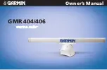
For the Yaw data collection two parallel lines are
used, with the vessel surveying in the same
direction on those lines. The lines are to be on
either side of a sea floor feature or over a slope.
The lines should be approximately 2 – 3 times
water depth in separation. A yaw error will result
in a depth position error, which increase with the
distance away from nadir.
Graph 3: Along track position error caused by 0.5° error in yaw patch test
-6
-4
-2
0
2
4
6
-80
-60
-40
-20
0
20
40
60
80
Alon
g-t
ra
ck
Po
siti
on
Er
ro
r
in
M
e
tr
es
Angle from Nadir
Position Error with a Heading Error of 0.50°
200 metres
150 metres
100metre
50 metre
25 metres
10 metres
Water Depth
Figure 86: Yaw data collection
Содержание 2022
Страница 1: ...SONIC 2024 2022 BROADBAND MULTIBEAM ECHOSOUNDERS Operation Manual V3 0 Part No 96000001 ...
Страница 2: ...Page 2 of 133 Version 3 0 Rev r000 Date 25 08 2010 Part No 96000001 ...
Страница 28: ...Page 28 of 133 Version 3 0 Rev r000 Date 25 08 2010 Part No 96000001 This page intentionally left blank ...
Страница 70: ...Page 70 of 133 Version 3 0 Rev r000 Date 25 08 2010 Part No 96000001 This page intentionally left blank ...
Страница 72: ...Page 72 of 133 Version 3 0 Rev r000 Date 25 08 2010 Part No 96000001 This page intentionally left blank ...
Страница 92: ...Figure 78 Smooth log information copied from real time survey log ...
Страница 96: ...Page 96 of 133 Version 3 0 Rev r000 Date 25 08 2010 This page intentionally left blank ...
Страница 112: ...Page 112 of 133 Version 3 0 Rev r000 Date 25 08 2010 This page intentionally left blank ...
Страница 116: ...Page 116 of 133 Version 3 0 Rev r000 Date 25 08 2010 This page intentionally left blank ...
Страница 124: ...Page 124 of 133 Version 3 0 Rev r000 Date 25 08 2010 Part No 96000001 Figure 93 Sonic 2024 2022 Projector ...
Страница 125: ...Page 125 of 133 Version 3 0 REV r000 Date 25 08 2010 Figure 94 Sonic 2024 Receive Module ...
Страница 126: ...Page 126 of 133 Version 3 0 Rev r000 Date 25 08 2010 Part No 96000001 Figure 95 Sonic 2022 Receive Module ...
Страница 127: ...Page 127 of 133 Version 3 0 REV r000 Date 25 08 2010 Figure 96 Sonic 2024 Mounting Bracket Drawing 1 ...
Страница 128: ...Page 128 of 133 Version 3 0 Rev r000 Date 25 08 2010 Part No 96000001 Figure 97 Sonic 2024 Mounting Bracket Drawing 2 ...
Страница 129: ...Page 129 of 133 Version 3 0 REV r000 Date 25 08 2010 Figure 98 Sonic 2022 Mounting Bracket Drawing 1 ...
Страница 130: ...Page 130 of 133 Version 3 0 Rev r000 Date 25 08 2010 Part No 96000001 Figure 99 Sonic 2022 Mounting Bracket Drawing 2 ...
Страница 131: ...Page 131 of 133 Version 3 0 REV r000 Date 25 08 2010 Figure 100 Sonic 2024 2022 Mounting Bracket Flange ...
Страница 132: ...Page 132 of 133 Version 3 0 Rev r000 Date 25 08 2010 Part No 96000001 Figure 101 SIM Box Drawing ...
Страница 133: ...Page 133 of 133 Version 3 0 REV r000 Date 25 08 2010 Figure 102 R2Sonic Deck lead minimum connector passage dimensions ...