background image

Radio Modem Box

10 / 29

User Manual

Rev. 1.0 - 24/06/04

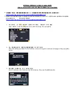
Figura 5.1

Follow the instructions provided below closely to ensure correct configuration of the

connection to PTX LCD with 16-bit CPU:

Содержание Radio Modem Box

Страница 1: ...Manufactured by Italy Radio Modem Box User Manual Volume 1 ...

Страница 2: ...pA Via del Fonditore 2 2c 40138 Bologna Italia Telefono 39 051 6010506 Fax 39 051 6011104 Email info rvr it Web www rvr it All rights reserved Printed and bound in Italy No part of this manual may be reproduced memorized or transmitted in any form or by any means electronic or mechanic including photocopying recording or by any information storage and retrieval system without written permission of...

Страница 3: ...ription of version with external UPS 5 4 2 Description of version with battery charger 7 5 Quick Guide Installation and Use 9 5 1 Preparation 9 5 2 Remote Alarm Reporting Configuration 12 5 3 Remote Control 17 5 4 SMS alarm test procedure 17 6 Controls Modules and Connectors 20 6 1 Front Panel 20 6 2 Rear Panel 20 6 3 Module identification top view 21 6 4 Connector Pinouts 23 7 Electric diagram la...

Страница 4: ...Radio Modem Box ii User Manual Rev 1 0 24 06 2004 This page was intentionally left blank ...

Страница 5: ...an cause hash In this case can be requested to user to take the necessary measures R V R Elettronica SpA reserves the right to modify the design and or the technical specifications of the product and this manual without notice 2 Warranty Any product of R V R Elettronica is covered by a 24 twenty four month warranty For components like tubes for power amplifiers the original manufacturer s warranty...

Страница 6: ... all the problems found and a copy of your original invoice establishing the starting date of the warranty Replacement and warranty parts may be ordered from the following address Be sure to include the equipment model and serial number as well as part description and part number R V R Elettronica SpA Via del Fonditore 2 2c 40138 BOLOGNA ITALY Tel 39 051 6010506 3 First Aid The personnel employed ...

Страница 7: ...ve or ointment Treat victim for shock as required Arrange transportation to a hospital as quickly as possible If arms or legs are affected keep them elevated If medical help will not be available within an hour and the victim is conscious and not vomiting give him a weak solution of salt and soda 1 level teaspoonful of salt and 1 2 level teaspoonful of baking soda to each quart of water neither ho...

Страница 8: ...SCM1 1 LCD SCMN 1 LCD PTX LCD with 16 bit CPU Radio Modem BOX has been designed to interface directly with systems comprising PTX LCD with 16 bit CPU for telemetry management and PJ amplifier or other non RVR amplifier and incorporates all necessary connections for both telemetry and mains management The front panel of Radio Modem Box features two RS232 DB9 connectors for direct connection both to...

Страница 9: ...seudo sine waveform Frequency from battery 50 60 Hz autorange 1 Hz SYSTEM Operation time 3 ms AC AC efficiency 98 Battery and runtime Lead battery maintenance free 10 min runtime at half load Protections Excessive discharge from accumulators over current short circuit temperature There are several different UPS types available in the market to meet specific application requirements Stand by Innorm...

Страница 10: ...is design avoids any delay in terms of load switching time Example of external UPS version connection to PTX LCD 220VAC MAINS IN MAINS IN 220VAC IN UPS IN UPS OUT UPS OUT RADIO MODEM BOX POWER AMP PTXLCD con cpu16bit UPS UNIT REMOTE TELEMETRY AMP TELEMETRY PTX REMOTE RS232 RS232 Example of external UPS version connection to TLC300 220VAC MAINS IN MAINS IN 220VAC IN UPS IN UPS OUT UPS OUT RADIO MOD...

Страница 11: ...non R V R Elettronica device using the Ext Telemetry terminal board as it incorporates all necessary connections for both telemetry and mains management The following R V R Elettronica amplifiers are suitable for connection to Radio Modem Box PJ300M PJ501M PJ500M PJ1000M PJ1000C LCD PJ2000M C All HC LCD couplers are compatible with Radio Modem Box Example of connection to PTX LCD 220VAC MAINS IN 2...

Страница 12: ...odem Box 8 29 User Manual Rev 1 0 24 06 04 Example of connection of version with battery charger to a system with TLC300 220VA MAINS IN 24VDC IN 24VDC OUT RADIO MODEM BOX TLC300 MAINS IN RS232 RS232 MAINS OUT ...

Страница 13: ... to one of the configurations described in Section 4 If you wish to change the type of amplifier connected or if amplifier type was not specified on order please refer to table 5 1 for dipswitch SW1 setting see Main Card wiring diagram 6 3 0 3 0 GLJ PHWHU 3 0 GLJ PHWHU 3 3 0 DQD 0HWHU DQD 0HWHU 3 0 3 0 2 21 21 2 21 21 21 2 2 21 2 2 21 21 2 2 2 21 21 21 2 2 2 21 Table 5 1 The SIM card to be inserte...

Страница 14: ...Radio Modem Box 10 29 User Manual Rev 1 0 24 06 04 Figura 5 1 Follow the instructions provided below closely to ensure correct configuration of the connection to PTX LCD with 16 bit CPU ...

Страница 15: ...ctory settings are as follows MAINS 10 sec FWD 15 sec RFL 15 sec If the Radio Modem Box is connected to a PTX LCD with external amplifier alarm time factory settings are as follows MAINS 10 sec Ext FWD 15 sec Ext RFL 15 sec Mains alarm time must always be lower than FWD and RFL time When finished place PTX LCD back into REMOTE mode 14 Disconnect the PC connection cable and connect the supplied DB9...

Страница 16: ... Configuration Firstly you will have to programme certain Radio Modem Box parameters using the TELECON software To this end connect the PC serial port COM to the RS232 connector on Radio Modem Box front panel using a standard Male DB9 Female DB9 serial cable When using the TELECON software for the first time select the station and then enter COM port used Baud rate 9600 type of connection direct v...

Страница 17: ...Radio Modem Box 13 29 User Manual Rev 1 0 24 06 04 Double click the green label in the top left corner of the TELECON screen and select Eeprom as shown in the next figure ...

Страница 18: ...max 18 characters DIAL STRING required setting for a GSM modem is ATDT NUMBER OF RETRY number of alarm transmission ripetitions SERVICE CENTER NUMBER number of GSM provider service center for SMS transmission and reception place country code before number Example with Italian service providers TIM 393359609600 VODAFONE 393492000200 WIND 393205858500 Now select the Telephone data category and set t...

Страница 19: ...o enable SMS reception ACS select YES to enable transmission of SMS commands to system MODEM select GSM Note For correct transmission place country code XX before set numbers Use 39 for Italy In systems with SCM TLC or with PTX LCD incorporating the telemetry option user programmable alarms are available and are managed by selecting the INPUTS data category ...

Страница 20: ...disable When all parameters are set press this key and the device connected to Radio Modem Box will store the information When finished click Exit to exit the remote station programming window Back into TELECON standard interface click the General measurement selection button to set thresholds and operation times for the various alarms according to the principles outlined in Section Alarm Manageme...

Страница 21: ...ta evaluation to locate possible faults identification of parts required for repair 5 4 SMS alarm test procedure This section describes the test procedure for SMS alarms in a system comprising PTX LCD with 16 bit CPU Initial configuration 1 Perform the steps described in paragraphs 5 1 and 5 2 2 Go to the MODEM menu of PTX LCD and ensure that state is Stby and provider details service centre and n...

Страница 22: ...me on to indicate successful alarm acquisition 5 The wording TX SMS appears on PTX LCD display in the MODEM menu 6 Wait until message MAINS absent is received 7 Wait for PTX LCD shut down triggered by Radio Modem Box time out 8 Put power back to the system PTX LCD Radio Modem Box 9 The GENERAL LED on the PTX LCD panel is off to indicate that no alarm condition is present 10 Wait for a time period ...

Страница 23: ...riggered A missing audio signal is a signal generating a modulation lower than 15KHz Note on alarm thresholds All alarm thresholds are based on the maximum value the machine will allow Example PTX30LCD FWD 100 30W RFL 100 3W PTX100LCD FWD 100 100W RFL 100 10W PTX30LCD PJ1000 Ext FWD 100 1000W Ext RFL 100 100W PTX30LCD PJ2000 Ext FWD 100 2000W Ext RFL 100 200W This means that a 50 setting in FWD or...

Страница 24: ...ture expansion 3 MODEM N C Provided for future expansion 4 DISPLAY N C Provided for future expansion 5 SMS N C Provided for future expansion 6 COM N C Provided for future expansion 7 RS 232 N C Provided for future expansion 8 LOCAL N C Provided for future expansion 9 RS 232 DB9 connector connected to telemetry unit PTX LCD SCM TLC PC 10 MODEM connector connected to GSM Modem PC Radio Modem Box 6 2...

Страница 25: ...nica units 8 TELEMETRYAMPL DB25 connector for telemetry connection to R V R Elettronica amplifiers 9 PTX LCD REMOTE DB15 connector for telemetry connection to PTX LCD 10 RS 485 N C Provided for future expansion 11 RS 232 DB9 connector for communication interface to external devices 12 I2 C BUS DB9 connector for I2 C communication 6 3 Module identification top view Radio Modem Box with battery char...

Страница 26: ...v 1 0 24 06 04 Radio Modem Box with UPS Figure 6 2 1 MAIN CARD Mains card SLINTBOXGSM1 2 MODEM Wavecom GSM modem 3 TRANSFORMER 30VAtransformer 4 ANTENNAFILTER GSM band filter 5 UPS IN VDE Connector for UPS input incorporates two 1 A fuses ...

Страница 27: ...with Dip7 OFF Dip8 ON 3 GND GND 4 Rfl Pwr T Ana In Reflected Power 5 IN_EXCT Dig In OC Active in the event of exciter interlock 6 N C 7 N C 8 OC_ONT Dig Out Command ON 9 N C 10 N C 11 N C 12 N C 13 N C 14 N C 15 IPA Ana In with Dip7 ON and Dip8 OFF 16 FWD PWR T Ana In Forward Power 17 TEMPALARM Dig In Dip3 OFF Dip3 ON with R Pullup 18 SWRALARM Dig In Dip4 OFF Dip4 ON with R Pullup 19 INP_PWR AMP D...

Страница 28: ... C 2 TXD 3 RXD 4 N C 5 GND 6 N C 7 N C 8 N C 9 N C 6 4 3 I2 C Connector Type DB9 Male 1 NC 2 SDA Serial Data 3 SCL Serial Clock 4 NC 5 GND GND 6 NC 7 NC 8 NC 9 NC 6 4 4 Ext Telemetry Type 8 Pin terminal board 1 FWD PWR IN 2 RFL PWR IN 3 VPA IN 4 IPA IN 5 TEMPALARM IN 6 SWRALARM IN 7 MAINSALARM OUT 8 GND Notes Pin 7 will output 0 V if an alarm signal is present on Mains ...

Страница 29: ...HYLVLRQH RGLFH 1RPH 3DUWH XWRUL D LRQH 3DJLQD 6L H GL 87B659 352 77 6FKHPD D EORFFKL EDWW LQW 5DGLR 0RGHP R 595 LXOLR HFFLDQL ULGD XQH 1RPH 3URJHWWR XWRUH RGLFH 3URJHWWR 1RPH 3 LQ 5HWH LOH DUWHOOD DWD 5HYLVLRQH RGLFH 1RPH 3DUWH XWRUL D LRQH 3DJLQD 6L H GL 87B659 352 77 6FKHPD D EORFFKL EDWW LQW 5DGLR 0RGHP R 595 LXOLR HFFLDQL ULGD XQH 9 0DLQV OLPHQWDWRUH SHU FDULFDEDWWHULH DULFDEDWWHULH 9 LOWUR 60...

Страница 30: ...5HYLVLRQH RGLFH 1RPH 3DUWH XWRUL D LRQH 3DJLQD 6L H GL 87B659 352 77 6FKHPD EORFFKL 836 LQW 5DGLR 0RGHP R 595 LXOLR HFFLDQL ULGD XQH 1RPH 3URJHWWR XWRUH RGLFH 3URJHWWR 1RPH 3 LQ 5HWH LOH DUWHOOD DWD 5HYLVLRQH RGLFH 1RPH 3DUWH XWRUL D LRQH 3DJLQD 6L H GL 87B659 352 77 6FKHPD EORFFKL 836 LQW 5DGLR 0RGHP R 595 LXOLR HFFLDQL ULGD XQH 9 5HOq SHU FRQWDWWR 0DLQV 7HOHPHWULD LOWUR 60 SDVVD EDQGD OLPHQWDWRU...

Страница 31: ...PS ODUP 2Q FRQ SXOOXS 2II VHQ D SXOOXS 6 5 ODUP 2Q FRQ SXOOXS 2II VHQ D SXOOXS 2Q 2II 93 VX SLQ 2II 2Q 93 VX SLQ 2Q 2II 3 VX SLQ 2II 2Q 3 VX SLQ 6 H 2Q SURJUDP PRGH H 2II QRUPDO PRGH H 1RQ XVDWL RQ FDULFDEDWWHULD FRUWRFLUFXLWDUH 6HQ D FDULFDEDWWHULD FRUWRFLUFXLWDUH 1 9 EDWWHULD 1 9 PRGHP 60 1 9 RFFROH 37 1 9 RQWDWWR PDLQV 1 3 670 6 3 670 6 1 1 Q Q FZ 59 FZ 59 5 5 6 6 17 60 2 6 6 17 60 2 5 5 5 5 5 ...

Страница 32: ...Radio Modem Box Rev 1 0 24 06 04 Layout Main card 28 29 ...

Страница 33: ...PP X 9 RQG OHWWU LD 3 1 RQG OHWWU LD 3 Q RQG 3ROLHVWHUH S PP X RQG 3ROLHVWHUH S PP PP 3RQWH GLRGL 8 1 LRGR SODVWLFR 2 RUR ILVVDJJLR PP 86 XVLELOH DXWRULS PP 3 3 3 1 3 RQQHWWRUH SROL ODW FV 3 670 6 6WULS PDVFKLR SLQ 60 3DG 60 D VDOGDUH 4 7 3 7UDQV 313 72 4 7UDQV 313 72 5 5 5 5 LVVLSDWRUH 72 59 59 7ULPPHU 5J 9 59 7ULPPHU 5J 5 5 74 9 5HOH 74 5 5 B7 9 5HOH VHULH HPH 7 5 5HV 5 5HV 5 5HV 5 5HV 5 1 5HV 5...

Отзывы: