

ISO
|
7
PREPARATION
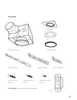
Before beginning assembly of product, make sure all parts are
present. Compare parts with package contents list and hardware
contents lists. If any part is missing or damaged, do not attempt
to assemble the product.
Estimated assembly time: one hour.
Tools required for assembly (not included): drywall saw, 4”
Phillips head drill bit, electric drill, stud finder, #1 drive Phillips
head screwdriver, standard face plate for light switch.
WARNING:
Turn off electricity at breaker box before
beginning installation.
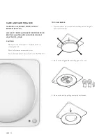
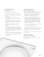
• Carefully remove unit from carton.
• Check area above installation location to be sure that wiring
can run to the planned location, ductwork can be run, and
the area is sufficient for proper ventilation. If duct cannot
be run away from ceiling or there is no duct, consult with a
professional before installing.
• Inspect ductwork and wiring before proceeding with installation.
• Before installation, make sure there is an accessible area for
future maintenance access.
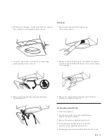
• You may need the help of a second person to install this fan;
one person on the attic side and the one on the bathroom side.
Note:
Installation may vary depending on how the previous bath
fan was installed. Supplies necessary for the installation of your
bath fan are not all included; however, most should be available
at your local home improvement or hardware store.
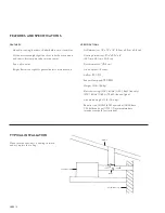
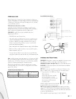
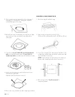
The hole for installation is not sized to the fan unit – use the
following dimensions so that the Iso ceiling panel will rest flush
against the ceiling.
DIMENSION REQUIREMENTS
Ceiling Opening
(L)
Ceiling Opening
(W)
Ceiling Opening
(H)
10.0 in. (25.4 cm)
10.0 in (25.4 cm)
8.0 in (20.3 cm)
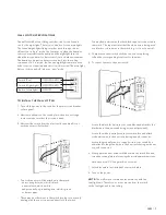
FAN WIRING DIAGRAM
WIRING INSTRUCTIONS
LIGHT HOUSING
FAN HOUSING
CONTROLLER
PCBA
UP TO 13 WATTS
UP TO 13 WATTS
AUTOMATIC TERMINAL SWITCH
MOTOR
GREEN WIRE TO GROUND
CAPACITOR
FOR LONG
LIFE OF FAN
WHITE WIRE TO NEUTRAL
BLACK WIRE TO LIVE
WARNING:
Wiring must comply with applicable electrical codes.
Turn OFF power before removing or installing wire nuts.
WARNING: Copper to copper only.
Do not use aluminium wire.
CAUTION:
Accessory part (wires nuts) should meet installation
instructions below.
NOTE:
The wire nut is reusable on solid wire of the same wire
gage or smaller, do not reuse the wire nut on stranded wires.
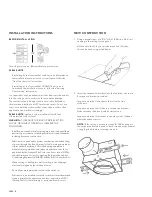
• Strip wires 3/8˝ – 1/2˝ (0.95 cm – 1.3 cm)
• Take both wires
(from wall and from new switch)
and twist together securely.
Insert secured wires into wire nut.
• Verify wires are fully inserted
into the wire nut.
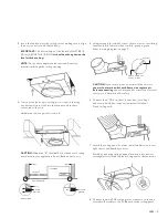
Further wiring instructions are included
in the Installation Instructions section.
NOTE – Important wire information:
Maximum temperature
rating 221°F (105°C). 600 volts maximum for building wire and
1000 volts maximum for building wire and 1000 volts maximum
in signs and lighting fixtures.
The acceptable wire range includes: Solid: 12–18 AWG
WIRE NUT
PRODUCT
WIRES
HOUSE
WIRES
BLACK WIRE
TO LIVE
WHITE WIRE
TO NEUTRAL
GREEN WIRE
TO GROUND
Содержание ISO
Страница 2: ...ISO 2...


