GSM/GPRS/GNSS Module Series
MC60 Series Hardware Design
MC60_Series_Hardware_Design Confidential / Released 24 / 114
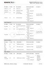
Pin Name
Pin No.
I/O
Description
DC Characteristics
Comment
PCM_CLK
59
DO
PCM clock
V
IL
min= 0V
V
IL
max=
0.25 × VDD_EXT
V
IH
min=
0.75×VDD_EXT
V
IH
max=
0.2
V
OH
min=
0.85×VDD_EXT
V
OL
max=
0.15 × VDD_EXT
If unused, keep
these pins open
PCM_OUT
60
DO
PCM data output
PCM_SYN
C
61
DO
PCM frame
synchronization
PCM_IN
62
DI
PCM data input
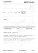
SD Card Interface
Pin Name
Pin No.
I/O
Description
DC Characteristics
Comment
SD_CMD
7
DO
Command signal of SD
card
V
IL
min=0V
V
IL
max=
0.25 × VDD_EXT
V
IH
min=
0.75 × VDD_EXT
V
IH
max=
0.2
V
OH
min=
0.85 × VDD_EXT
V
OL
max=
0.15 × VDD_EXT
If unused, keep
these pins open
SD_CLK
8
DO
Clock signal of SD card
SD_DATA
9
IO
Data signal of SD card
Antenna Interface
Pin Name
Pin No.
I/O
Description
DC Characteristics
Comment
RF_
ANT
41
IO
GSM antenna pad
Impedance of 50Ω
BT_
ANT
32
IO
BT antenna pad
Impedance of 50Ω
If unused, keep
this pin open
GNSS_
ANT
15
AI
GNSS signal input
Impedance of 50Ω
Other Interface
Pin Name
Pin No.
I/O
Description
DC Characteristics
Comment
GNSS_
VCC_EN
28
DO
GNSS power enabled
V
OH
min=
0.85 × VDD_EXT
V
OL
max=
0.15 × VDD_EXT
1. Refer to
Chapter
3.5.3.2
in
All-in-one
solution.
Quectel
Confidential


