background image


GNSS  Module  Series 

LC29D_EVB(0)_User_Guide                                                                                                                      26  / 42 


7.1.1. 

Get RTCM Data through QGNSS Tool 

7.1.1.1. 

Hardware Link Connection 

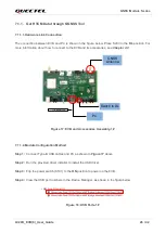
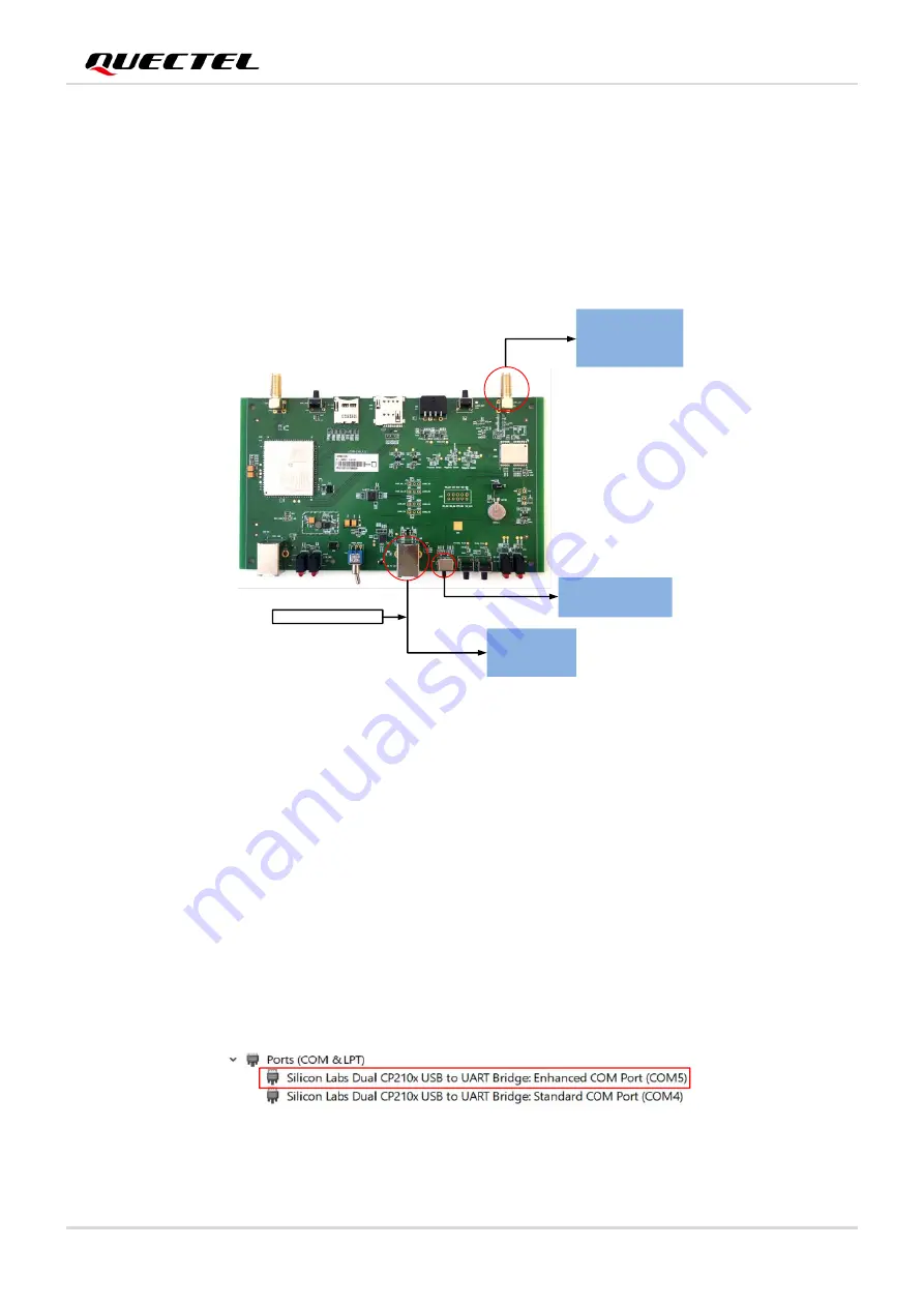
The connection between EVB and PC is shown in the figure below. Place S203 in the 

DL

 position. For 

more information about how to connect to the EVB and its accessories, see 

Chapter 2.2

PC

Type-B USB cable

GNSS 

Antenna

Switch to DL


Figure 17: EVB and Accessories Assembly-1# 


7.1.1.2. 

Module Configuration Method 

Step 1: 

Connect Type-B USB cables and PC as shown in 

Figure 17 

above. 


Step 2: 

Run the provided driver installer to install the USB driver. 


Step 3: 

Flip the power switch (S101) to the 

ON

 position to power on the EVB. 


Step 4: 

View the USB port numbers in the Device Manager, as shown in the figure below. 


Figure 18: USB Ports-1#


Содержание LC29D

Страница 1: ...LC29D EVB 0 User Guide GNSS Module Series Version 1 0 Date 2021 07 06 Status Released ...

Страница 2: ...imer While Quectel has made efforts to ensure that the functions and features under development are free from errors it is possible that these functions and features could contain errors inaccuracies and omissions Unless otherwise provided by valid agreement Quectel makes no warranties of any kind implied or express with respect to the use of features and functions under development To the maximum...

Страница 3: ...smitting reproducing disseminating and editing this document as well as using the content without permission is forbidden Offenders will be held liable for payment of damages All rights are reserved in the event of a patent grant or registration of a utility model or design Copyright Quectel Wireless Solutions Co Ltd 2021 All rights reserved ...

Страница 4: ...ese precautions Ensure that the product may be used in the country and the required environment as well as that it conforms to the local safety and environmental regulations Keep away from explosive and flammable materials The use of electronic products in extreme power supply conditions and locations with potentially explosive atmospheres may cause fire and explosion accidents The product must be...

Страница 5: ...e Document Revision History Document Information Title LC29D EVB 0 User Guide Subtitle GNSS Module Series Document Type EVB User Guide Document Status Released Version Date Description 2021 03 29 Creation of the document 1 0 2021 07 06 First official release ...

Страница 6: ...ort and Baud Rate Setting 18 5 1 1 Interface Explanation 19 5 2 Automatic TTFF Testing 21 6 DR Application 24 7 RTK Application 25 7 1 Connecting to Base Station 25 7 1 1 Get RTCM Data through QGNSS Tool 26 7 1 1 1 Hardware Link Connection 26 7 1 1 2 Module Configuration Method 26 7 1 1 3 RTK Account Configuration Method 28 7 1 2 Get RTCM Data through EG25 G Module 29 7 1 2 1 Hardware Link Connect...

Страница 7: ... Detailed EVB Interfaces 12 Table 3 J302 Pin Detailed Description 14 Table 4 J501 Pin Detailed Description 15 Table 5 Explanation of QGNSS Interface 19 Table 6 NTRIP Client Parameter 29 Table 7 Parameter 32 Table 8 Quality Parameter 33 Table 9 Related Documents 40 Table 10 Terms and Abbreviations 40 ...

Страница 8: ...gure 17 EVB and Accessories Assembly 1 26 Figure 18 USB Ports 1 26 Figure 19 QGNSS Setting 1 27 Figure 20 QGNSS Interface Connected 1 27 Figure 21 Configure RTK Account 1 28 Figure 22 RTCM Data Acquisition Successful 1 28 Figure 23 EVB and Accessories Assembly 2 30 Figure 24 USB Ports 2 30 Figure 25 QGNSS Setting 2 31 Figure 26 QGNSS Interface Connected 2 31 Figure 27 QGNSS Setting AT Port 32 Figu...

Страница 9: ... Kit accessories Chapter 3 describes the EVB user interfaces Chapter 4 describes how to communicate with the module by using the QCOM tool Chapter 5 describes how to test the module by using the QGNSS tool Chapter 6 describes how to configure the LC29D DR Chapter 7 introduces how to use the LC29D RTK Chapter 8 describes how to upgrade firmware Chapter 9 is an appendix which summarizes the relevant...

Страница 10: ...e B USB Cables and Bolts and Coupling Nuts You can request the software tools from our website www quectel com The EVK Kit accessories are shown in the figure below Check Table 1 for details LC29D active GNSS antenna Type B USB cable Type B USB cable Bolts and coupling nuts EG25 G antenna EVB Figure 1 EVK Kit Accessories The EVB version is LC29D EVB_V1 2 NOTE ...

Страница 11: ...uction sheet inside the EVB Kit Figure 2 EVB and Accessories Assembly Place the active GNSS antenna where it can detect the satellites with a clear view of the sky Item Description Quantity EVB Evaluation Board Size 100 mm 175 mm 1 USB Cable Type B USB Cables 2 GNSS Antenna LC29D Active GNSS Antenna Request the Antenna Datasheet from our website www quectel com 1 EG25 G Antenna Request the Antenna...

Страница 12: ...nnector J404 U SIM card connector J501 ODO connector S301 LC29D_BOOT button J301 LC29D_ANT connector U301 LC29D module J302 Test points D301 1PPS and TXD indication LEDs S201 RESET_N S203 DL RTK switch J201 USB to UART S101 POWER_SWITCH D403 EG25 G status and netlight indication LEDs J101 EG25_USB U401 EG25 G module D104 Power indication LEDs D302 GEO and RTK indication LEDs Figure 3 EVB Top View ...

Страница 13: ...load Switch S203 to the DL side when a firmware download or testing of RTK via PC is needed Standard COM Port Be used for LC29D module NMEA output and command input Switch S203 to the RTK side when testing RTK with the EG25 G module The premises are that the EG25 G module configures the RTK function and the SD card and U SIM card are inserted RF Input J301 LC29D_ANT Antenna Connector Support GPS Q...

Страница 14: ...icker quickly 125 ms High 125 ms LOW Data transfer is ongoing Always high Voice calling Switches and Buttons S101 POWER_SWITCH Power the EVB on off S201 RESET_N Short press the button to reset the LC29D module S401 EG25_RESET Short press the button to reset the EG25 G module S203 DL RTK Switch DL LC29D UART is connected to Enhanced COM Port and will be used for configuring LC29D module and downloa...

Страница 15: ...K FWD GND J202 SD Card Connector The data received by the SD card and Standard COM Port are the same Test Points J302 Test Points Pins are detailed in Table 3 below J501 ODO Connector Pins are detailed in Table 4 below Pin Name I O Description VDD_EXT Reserved CTS1 DO Clear to send RTS1 DO Request to send TXD1 DO Transmits data RXD1 DI Receives data I2C_SDA Reserved I2C_SCL Reserved 1PPS DO 1 puls...

Страница 16: ...odule Series LC29D_EVB 0 _User_Guide 15 42 Table 4 J501 Pin Detailed Description Pin Name I O Description NC NC NC NC NC WHEELTICK DI Odometer wheel tick input FWD DI Forward Backward signal input GND Ground ...

Страница 17: ...ype B USB cables via the Type B USB interface as shown in Figure 2 Step 2 Flip the power switch S101 to the ON position to power on the EVB Step 3 Run the provided driver installer to install the USB driver Step 4 View the USB port numbers in the Device Manager as shown in Figure 4 below Figure 4 USB Ports Step 5 Install the QCOM tool provided by Quectel The COM Port Setting interface of QCOM is s...

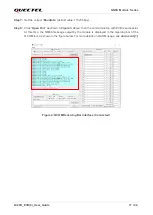
Страница 18: ... Click Open Port as shown in Figure 5 above then the communication with EVB is successful At this time the NMEA message output by the module is displayed in the receiving bar of the QCOM tool as shown in the figure below For more details on QCOM usage see document 1 Figure 6 QCOM Receiving Bar Interface Connected ...

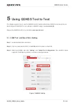
Страница 19: ... details on QGNSS usage see document 3 Request the QGNSS tool from our website www quectel com 5 1 COM Port and Baud Rate Setting Step 1 Assemble the EVB Accessories Step 2 Flip the power switch S101 to the ON position to power on the EVB Step 3 Start the QGNSS and click Setting and Serial Port Configuration the LC29D module supports 115200 bps by default as shown in the figure below Figure 7 QGNS...

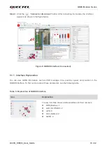
Страница 20: ... Interface Connected 5 1 1 Interface Explanation You can view GNSS information such as CNR message time position speed and precision in the QGNSS interface To find out more about these parameters see the following table Table 5 Explanation of QGNSS Interface Icon Explanation The sky interface shows visible satellites and their numbers BDS BeiDou 7 GLO GLONASS 2 GPS 8 GAL Galileo 2 QZSS 2 ...

Страница 21: ...right red means that the navigation data of the satellite is in use PRN 1 CNR is 21 dB Hz Column in light red means that the navigation data of this satellite is not in use Longitude degree Latitude degree Altitude MSL Altitude EPH Receiver speed Horizontal dilution of precision Position dilution of precision FixMode UTC date and time Total number of seconds Last TTFF s Quality Indicator Total Tim...

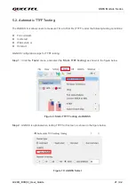
Страница 22: ...ing testing conditions Full cold start Cold start Warm start or Hot start QGNSS configuration steps for TTFF testing Step 1 Click the Tools menu and select the Static TTFF Testing as shown in the figure below Figure 9 Static TTFF Testing via QGNSS Step 2 AGNSS is optional when testing TTFF for this tool as shown in the figure below Figure 10 AGNSS Select ...

Страница 23: ...ear Stop button to clear the data and stop the test Figure 11 The Number of Testing Step 4 If you select hot start it is recommended to set the TTFF Timeout seconds to 10 s If you select warm start you can set the TTFF Timeout seconds to 50 s Or if you select cold start you can set the TTFF Timeout seconds to 100 s TTFF Timeout seconds can help you to assess TTFF and save time Figure 12 Set TTFF T...

Страница 24: ...tton to start the test OR Click on the Stop button to stop the test Figure 13 Run or Stop Test Step 6 View the test results displayed visually in charts as shown in the figure below The test results are stored in the directory where the tool is installed Figure 14 Test Results ...

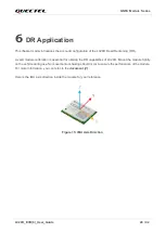
Страница 25: ...valid module calibration is essential for utilizing the DR capabilities of LC29D Mount the module tightly on the vehicle during use No movement or shaking should occur to ensure the performance of the module For more information you can refer to the document 2 Here is the IMU axis direction inside the module for your reference Figure 15 IMU Axis Direction ...

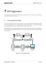
Страница 26: ...ally provided by a host from base stations The host runs an NTRIP client and streams RTCM corrections to the LC29D module through a UART Two major ways to connect to base stations are shown in the figure below one is using the QGNSS tool which only supports adopting the NTRIP protocol to obtain server base station data and the other is using a cellular module Cellular Module GNSS Module Base Stati...

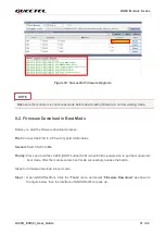
Страница 27: ...d its accessories see Chapter 2 2 PC Type B USB cable GNSS Antenna Switch to DL Figure 17 EVB and Accessories Assembly 1 7 1 1 2 Module Configuration Method Step 1 Connect Type B USB cables and PC as shown in Figure 17 above Step 2 Run the provided driver installer to install the USB driver Step 3 Flip the power switch S101 to the ON position to power on the EVB Step 4 View the USB port numbers in...

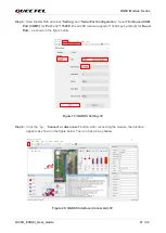
Страница 28: ...OM Port COM5 for Port and 115200 the LC29D module supports 115200 bps by default for Baud Rate as shown in the figure below Figure 19 QGNSS Setting 1 Step 6 Click the Connect or disconnect button After connecting the module the interface appears as shown in the figure below The icon has a blue shadow Figure 20 QGNSS Interface Connected 1 ...

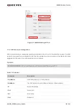
Страница 29: ... Step 2 Set RTK account configuration information in the NTRIP Client interface Figure 21 Configure RTK Account 1 Step 3 After entering the corresponding configuration information click Connect You can see the text output is displayed as shown in the figure below Send GGA to server and Received 570 bytes from server which indicate that the RTCM data acquisition is successful Figure 22 RTCM Data Ac...

Страница 30: ...nt NTRIP mount point When using the QGNSS tool to configure RTK the PC side maintains a network connection 7 1 2 Get RTCM Data through EG25 G Module 7 1 2 1 Hardware Link Connection The connection between EVB and PC is shown in the figure below Place S203 in the RTK position and insert SD card into J202 and U SIM into J404 For more information about how to connect the EVB and its accessories see C...

Страница 31: ...tep 2 Run the provided driver installer to install the USB driver Step 3 Flip the power switch S101 to the ON position to power on the EVB Step 4 View the USB port numbers in the Device Manager as shown in the figure below Figure 24 USB Ports 2 Step 5 Start the QGNSS and click Setting and Serial Port Configuration Select Standard COM Port COM4 for Port and 115200 the LC29D module supports 115200 b...

Страница 32: ... After connecting the module the interface appears as shown in the figure below The icon has a blue shadow Figure 26 QGNSS Interface Connected 2 Step 7 Use the QGNSS tool to connect to the AT port COM10 as shown in the figure below The baud rate of the AT port is 115200 bps Connect the module as shown in Figure 26 above ...

Страница 33: ...s to be configured for the first time unless the account expires or the EG25 G module upgrades the firmware The commands format is as follows Synopsis AT QGNSSPARAM 0 0 ip port quectel_usr quectel_pwd mount_point 1 1 Table 7 Parameter Parameter Description ProtoMode 0 NTIRP protocol 1 TCP protocol DataMode The TCP protocol is valid 0 Rover Station 1 Base station IP Server IP address Port Server po...

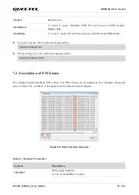
Страница 34: ... returned message will be QGNSSPARAM OK If there is any error the returned message will be QGNSSPARAM ERR 7 2 Description of RTK Status The chapter mainly describes RTK status The RTK status can be judged by the Quality parameter value in GGA The number 4 in the figure below represents fixed integers Figure 28 GGA Example Diagram Table 8 Quality Parameter Content Description Quality GPS quality in...

Страница 35: ...PS Mode fix valid 2 Differential GPS SPS Mode or Satellite Based Augmentation System SBAS fix valid 3 GPS PPS Mode fix valid 4 RTK System used in RTK mode with fixed integers 5 Float RTK Satellite system used in RTK mode floating integers 6 Estimated DR mode ...

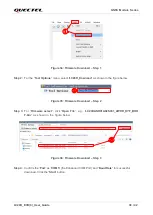
Страница 36: ...are upgrade process First Connect the EVB to a PC with Type B USB cables Second Flip the power switch S101 to the ON position to power on the EVB and switch S203 to DL Steps for firmware upgrade in normal working mode Step 1 Open GNSSFlashTool GNSSFlashTool_V1 13 is used as an illustration in this document Click Tools and select Firmware Download as shown in the figure below then the interface of ...

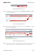
Страница 37: ...e figure below Figure 31 Firmware Upgrade Step 3 Step 4 Confirm the Port as COM5 the Enhanced COM Port and Baud Rate for successful download Click the Start button Figure 32 Firmware Upgrade Step 4 Step 5 When the firmware upgrade is successful the progress bar will indicate 100 and there will be a green rectangle on the screen GNSSFlashTool appears as shown in the figure below ...

Страница 38: ...d process First Connect the EVB to a PC with Type B USB cables Second Switch S203 to DL Thirdly Press and hold the LC29D_BOOT button S301 when EVB is powered on to put the module into boot mode After the module enters boot mode successfully release the button Steps for firmware download in boot mode Step 1 Open GNSSFlashTool Click the Tools menu and select Firmware Download as shown in the figure ...

Страница 39: ...ownoad as shown in the figure below Figure 35 Firmware Download Step 2 Step 3 For Firmware select click Open File e g LC29DANR01A02SV01_2WDR_HYF_BOO T bin as shown in the figure below Figure 36 Firmware Download Step 3 Step 4 Confirm the Port as COM5 the Enhanced COM Port and Baud Rate for successful download Click the Start button ...

Страница 40: ...ure 37 Firmware Download Step 4 Step 5 When the firmware download is successful the progress bar will indicate 100 and there will be a green rectangle on the screen GNSSFlashTool appears as shown in the figure below Figure 38 Successful Firmware Download ...

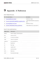
Страница 41: ...on_Note LC29D GNSS DR RTK 0 Application Note 3 Quectel_QGNSS_User_Guide QGNSS User Guide 4 Quectel_LC29D_GNSS_Protocol_Specification LC29D GNSS Protocol Specification Abbreviation Description BeiDou BeiDou Navigation Satellite System bps bits per second CEP Circular Error Probable CNR Carrier to noise Ratio COM Port Communication Port DI Digital Input DL Download DO Digital Output DR Dead Reckonin...

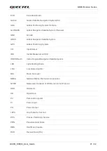
Страница 42: ... System I O Input Output IMU Inertial Measurement Unit IRNSS NavIC Indian Regional Navigation Satellite System LED Light Emitting Diode LNA Low Noise Amplifier MSL Mean Sea Level NMEA National Marine Electronics Association NTRIP Networked Transport of RTCM via Internet Protocol ODO Odometer OD Open Drain PC Personal Computer PI Power Input PO Power Output 1PPS One Pulse Per Second PPS Precise Pos...

Страница 43: ...me Services RTK Real Time Kinematic SBAS Satellite Based Augmentation System SPS Standard Positioning Service TCP Transmission Control Protocol TTFF Time to First Fix TXD Transmit Data Pin UART Universal Asynchronous Receiver Transmitter USB Universal Serial Bus UTC Coordinated Universal Time ...

Отзывы: