


LTE Standard Module Series
EG25-GL_Hardware_Design 35 / 96
To avoid corrupting the data in the internal flash, do not switch off the power supply when the module
works normally. Only after shutting down the module with PWRKEY or AT command can you cut off the
power supply.
3.3.4 Power Supply Voltage Monitoring
AT+CBC
can be used to monitor the VBAT_BB voltage value. For more details, see
document [2]
3.4 Turn On
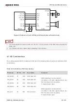
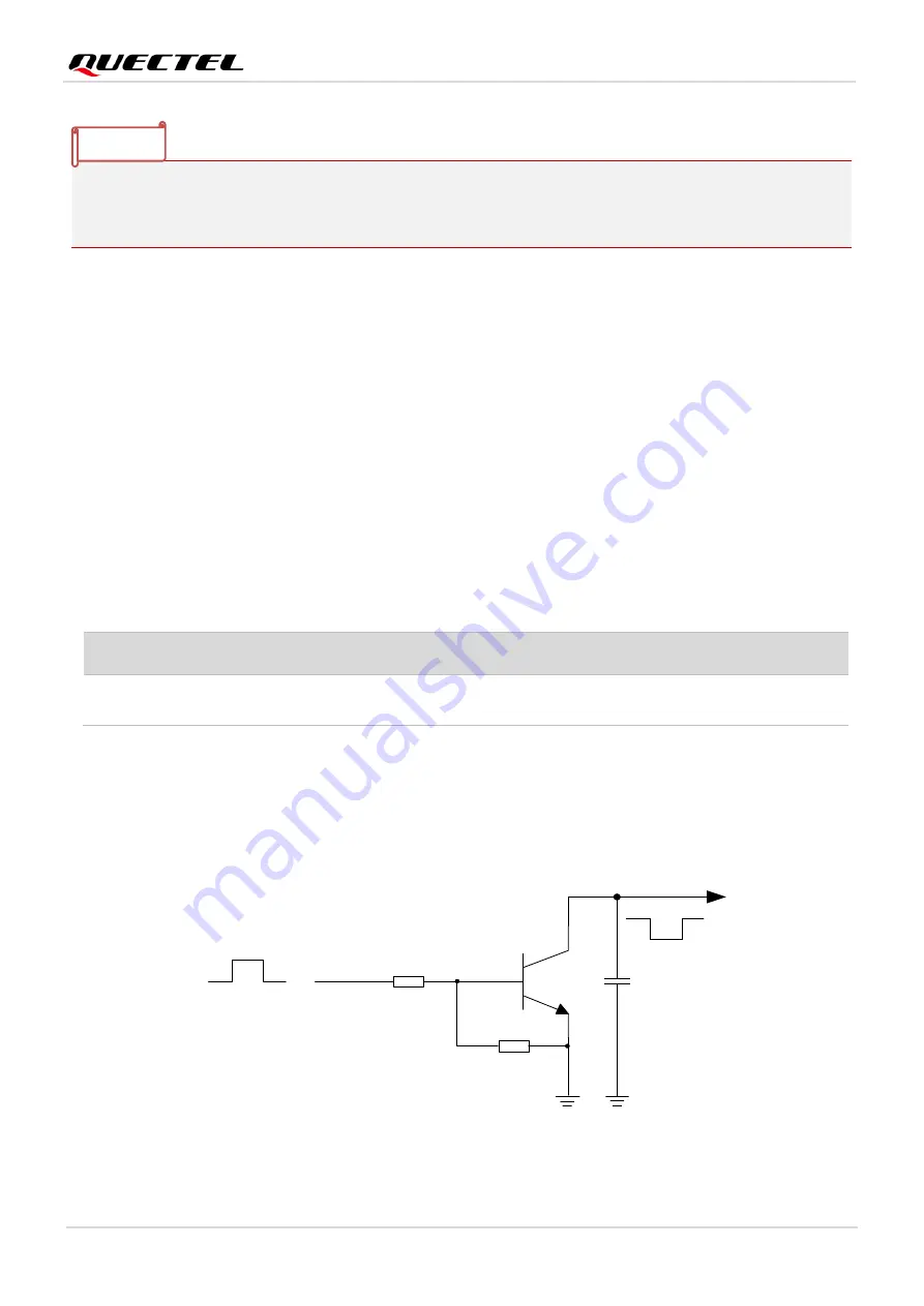
3.4.1 Turn On with PWRKEY
The following table shows the pin definition of PWRKEY.
Table 8: Pin Definition of PWRKEY
When the module is in power down mode, it can be turned on by driving PWRKEY low for at least 500 ms.
It is recommended to use an open drain/collector driver to control the PWRKEY. After STATUS pin
(requires external pull-up resistor) outputs a low level, PWRKEY pin can be released. A simple reference
circuit is illustrated in the following figure.
PWRKEY
4.7K
47K
Turn-on pulse
≥ 500 ms
10 nF
Figure 10: Turn On the Module by Using Driving Circuit
Pin Name Pin No.
I/O
Description
Comment
PWRKEY
21
DI
Turn on/off the module
The output voltage is 0.8 V because of the
diode drop in the chipset.
NOTE
Содержание EG25-GL
Страница 1: ...EG25 GL Hardware Design LTE Standard Module Series Version 1 0 0 Date 2022 09 09 Status Preliminary ...
Страница 8: ...LTE Standard Module Series EG25 GL_Hardware_Design 7 96 9 Appendix References 92 ...
Страница 10: ...LTE Standard Module Series EG25 GL_Hardware_Design 9 96 Table 42 Terms and Abbreviations 92 ...


