


3
rd
Generation Dual Channel
Compact RDMS
TM
Telemetry Receiver-Combiner
121
Quasonix, Inc.
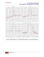
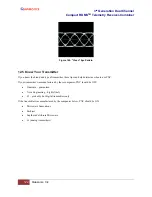
Figure 167: Trellis Detection Gain with Significant to Severe Phase Noise
12.2 Phase Noise Impact
Trellis demodulation is based on the assumption that the signal is following a predictable path through the trellis. If
this is not true (due to high phase noise), then a trellis demodulator cannot provide the expected performance gain.
•
Many legacy analog transmitters (a simple modulated VCO) have high phase noise.
•
Vibration often further increases phase noise.
•
Phase noise is generally more damaging at low bit rates.
•
Phase Noise Compensation (PNC) gives back some of the trellis detection gain, by shortening the trellis
observation span.
12.3 Clock Jitter Impact
Many older PCM encoders are susceptible to large inaccuracies in clock rate or have clock stability issues,
especially under harsh vibration conditions. While the RDMS is capable of tracking static clock rate errors as large
as 1000 ppM, excessive jitter causes the integrated bit sync to lose lock. Enabling the PNC mode opens the tracking
loop bandwidth to accommodate for these issues. This increase in bandwidth does have a tradeoff. A wider tracking
range allows the RDMS to deal with the additional jitter, but it may also increase synchronization times slightly, and
slightly increase the minimum SNR at which the RDMS declares lock.
12.4 When to Use PNC
There is no bullet-proof test for whether PNC is needed, but DQM is pretty close. The PNC Auto setting uses DQM
from both trellis and single-symbol demodulation to select which is providing better results for the present input
signal. The primary downside to PNC Auto is that there is time delay switching between PNC On and PNC Off.
Therefore, PNC Auto is ideal for cases where it is not obvious if PNC is needed, but it may not be suitable for cases
where phase noise is rapidly variable. Enable PNC Auto or PNC On if:
•
The demodulator is struggling to lock, even with good Signal to Noise Ratio (SNR). ("Good" SNR means
the signal strength bar with properly zeroed AGC is green.)
•
The eye pattern NEVER looks “clean,” as in Figure 168
•
Symptoms get worse when the transmitter is under vibration
•
Symptoms get worse at low bit rates


