


Quartz Q16/Q32 System Manual
18 May 2004
Issue 5.00
Page 28
1
2
3
4
UP UP DN UP
RESET
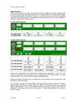
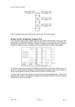
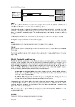
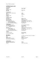
Baud Rate (DIP-1) :
This switch forces default baud rate (9600 or 38400), or allows the user to define a baud
rate using WinSetup. Up=Default, Down=User defined.
Computer Port (DIP-2) :
This switch sets the mode of operation of the computer port between diagnostics or
protocol mode. Normally the setting is for diagnostics mode so that the matrix outputs basic error logging
information. Use this mode with the WinSetup ‘PC Comms Window’ or any dumb terminal. The protocol mode
is used if a computer is being used to download a new system configuration from WinSetup, or if the matrix is to
be controlled from an external computer in a remote switching application. Up=Diagnostics, Down=Protocol.
Frame Priority (DIP-3) :
This switch determines the priority of the frames in the system. One frame must be
set as master and all the others as slaves. The master holds the configuration of the system that determines
how the system operates and also contains the non-volatile RAM that stores the status of the system.
Up=Slave, Down=Master.
Force Input at Power Up (DIP-4) :
The router system normally remembers the crosspoint settings after a power
loss. In some situations it may be preferable to restore the router to a defined input, say bars/tone, after a power
loss. This switch overrides the normal battery backed memory operation. Up=Battery backed, Down=Override
to specified input.
0
8
4
C
0
8
4
C
High
Low
Router
Processor
The reset switch must be pressed after changing the DIP switch.
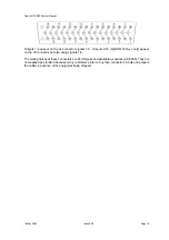
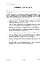
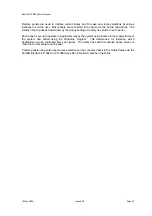
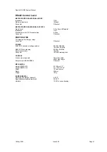
Status LED’s
There are a number of LED’s giving status information.
1
2
3
4
0
RESET
Pwr
OK
Rst
No
QL
Proc
OK
8
4
C
Reset :
This red LED indicates that the reset circuit has
been activated, either by the reset push button, after a
power loss, or because the processor watchdog timer has
tripped (software malfunction).
General Error :
This red LED indicates errors are
occurring on the Q-Link or on the serial (RS232/422) ports.
Processor Running :
This green LED flashes at 1Hz to
indicate that the processor is running (has not crashed).
Power OK :
This yellow LED indicates that the +5V power
supply to the processor circuit is OK.
Gen
Err
Xpt
Set
Ser
Rx
No Q-Link :
This red LED indicates that a slave device
is not receiving regular Q-Link messages. At power up
this LED should turn off once all slave devices are on-
line (up to 30 seconds) and then stay off.
Xpt Set :
This green LED indicates that a crosspoint has
been set on the router module(s) that this processor is
controlling (not used on control panels).
Serial Rx :
This green LED indicates that a message
has been received on the serial (RS232/422) port.
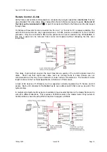
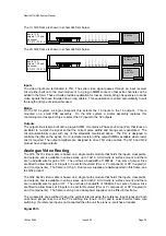
System Control Bus: Q-Link
The
Q-link
used to interconnect the panels and frames uses a single coaxial cable. This method was
chosen because it is the easiest for installation.
The
Q-link
is daisy-chained from one panel to the next and between the frames. Messages are sent
by injecting signal currents onto the link, to be received by all the other panels or frames on the line.
The link is terminated with 75
Ω
at both ends, as is standard video practice, and will not work without
at least one termination.
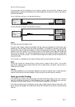
A
hex
switch in each frame and panel sets the identity of each so that they are correctly addressed by
the control system. A total of 64 devices (V5 firmware) can be supported normally organised as 16
frames and 48 panels.
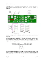
Two BNC sockets are provided on the frames fed from a single driver/receiver. Thus short lengths of
coax cable can be used to interconnect the frames in a multi-frame system by looping through the
frames. The panels are however fitted with just one BNC connector, as it is better practice to use a T-
piece to
tap off
the
Q-link
into the panels. In this way a panel can be removed from service without
the
Q-link
being interrupted.
A total run of over 500 metres of video cable can be used between panels and the frames. For
installations that require several long runs in different directions the CI-0004 module or SC-1000


