


Quartz Q16/Q32 System Manual
18 May 2004
Issue 5.00
Page 14
Relay Routers
There are two types of relay router, two pole and four pole, available in two different chassis sizes.
Two pole routers support two independent signals or one pair of signals. Four pole routers support
four independent signals or two pairs or signals. The chassis sizes are the Q16 (1U) supporting
matrix sizes up to 16x8 and the Q32 (2U) supporting matrix sizes up to 16x16. The Q32 chassis also
supports a redundant PSU where required.
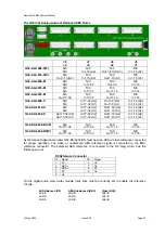
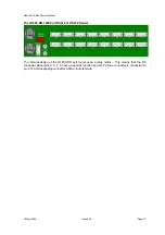
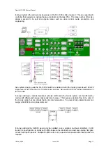
The Q16-RR Relay Router
J4 J3 J2 J1
Q16-RR-1608-02
Out 1-8 (pair 1)
N/C
In 1-16 (pair 1)
N/C
Q16-RR-1608-04
Out 1-8 (pair 1)
Out 1-8 (pair 2)
In 1-16 (pair 1)
In 1-16 (pair 2)
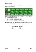
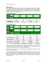
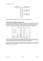
The Q32-RR Relay Router
J8
J4
J7
J3
J6
J2
J5
J1
Q32-RR-1608-02(P)
N/C
Out 1-8 (pair 1)
N/C
N/C
N/C
In 1-16 (pair 1)
N/C
N/C
Q32-RR-1608-04(P)
N/C
Out 1-8 (pair 1)
N/C
Out 1-8 (pair 2)
N/C
In 1-16 (pair 1)
N/C
In 1-16 (pair 2)
Q32-RR-1616-02(P)
Out 9-16 (pair 1)
Out 1-8 (pair 1)
N/C
N/C
External loop
In 1-16 (pair 1)
N/C
N/C
Q32-RR-1616-04(P)
Out 9-16 (pair 1)
Out 1-8 (pair 1)
Out 9-16 (pair 2)
Out 1-8 (pair 2)
In 1-16 (pair 1)
(a)
In 1-16 (pair 1)
In 1-16 (pair 1)
(a)
In 1-16 (pair 2)
Note (a): The 16x16 relay router is formed from 2 independent 16x8 modules. To work as a pair
the input signals from the J2 connector must be externally joined to the J6 connector. In a four
pole router the J1 and J5 connectors must also be externally joined.
Router sizes above 16x8 that are to be controlled only using the Serial connector must have a 75R
termination on the main Q-Link.
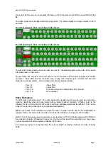
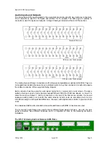
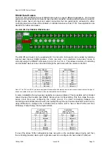
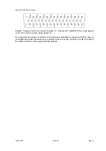
The connection of signals to the relay routers is made using 50 way multi-way connectors. The same
type or polarity of connector is used for inputs and outputs. The inputs are shown on the drawing
below as pairs labelled ‘+’ and ‘-‘ but the signals do not have to be pairs. When a route is made the
input pair 1 ‘+’ signal will be connected to the output pair 1 ‘+’ signal, and similarly for the ‘-‘ signal and
the pair 2 signals.


