Quantum IOT Series Скачать руководство пользователя страница 9

9

Installation

Cold water 

from Mains

Balanced Cold 

Water Supply

Expansion Vessel 

Connection

Cold Water Inlet

Expansion Relief 

Valve

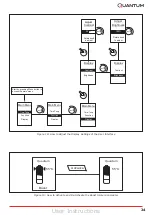
Figure 3: Detail Showing the Connection of the 

Expansion Vessel to the Inlet Group

If a balanced cold water supply is required a 

connection can be taken from the bottom of the 

inlet group. 

6.1.4 

Balanced Cold Water Supply

It is also recommended to install a drain valve 

(not supplied) in the lowest point of the cold water 

feed to the cylinder. This allows the cylinder to be 

drained in a controlled manner should this become 

necessary.

6.1.5 

Drain Valve

6.2 

Hot Water Outlet

The hot water pipework is to be directly 

connected to the hot water outlet connection on 

the cylinder.

A thermostatic mixing valve may be required to 

limit the outlet temperature. In this case, the 

valve should be installed following the 

manufacturer’s instructions, ensuring none of the 

safety equipment has been isolated, (i.e. make 

sure the connection to the thermostatic mixing 

valve is taken after the safety equipment of the 

inlet group).

6.2.1 

Thermostatic Mixing Valve

It is recommended to insulate the hot water pipe- 

work from the cylinder to the outlets, to reduce 

the energy requirements for providing hot water. 

It is also recommended to insulate all other 

exposed pipework, such as the T&P to the tundish, 

the coil flow and return and the cold water inlet 

pipes.

6.2.2 

Pipe Insulation

6.3 

Discharge Pipes from Safety Devices

The temperature and pressure relief valve must 

be discharged directly or by way of a manifold via 

a short length of metal pipe (D1) into a tundish; 

and the discharge pipe must be installed in a 

continuously downward direction and in a frost 

free environment. Water may drip from the 

discharge pipe of the pressure relief device and 

this pipe must be left open to the atmosphere.

The diameter of discharge pipe (D1) should not be 

less than the nominal outlet size of the safety 

device, e.g. temperature relief valve.

Where a manifold is used it should be sized to 

accept and discharge the total discharge from all 

the D1 discharge pipes connected to it.

The discharge pipework from the expansion relief 

valve must be installed constantly falling to an 

open point of discharge. It is recommended to 

combine it with the discharge of the temperature 

and pressure relief valve.

Note: The T&P valve is pre-sealed and if 

moved the seal will be broken, should this 

occur, it will need to be resealed with an 

appropriate sealant (Part number R00836-1)

6.3.1 

Discharge Pipe D1

The tundish should be vertical, located in the 

same space as the unvented hot water storage 

system and be fitted as close as possible to, and 

lower than, the safety device, with no more than 

600mm of pipe between the valve outlet and the 

tundish. 

Discharge should be visible at the tundish, where 

discharges may not be apparent, e.g. in dwellings 

occupied by people with impaired vision or 

mobility, consideration should be given to the 

installation of a suitable safety device to warn 

when discharge takes place, e.g. electronically 

operated.

Note: To comply with the Water Supply 

(Water Fittings) Regulations, the tundish 

should incorporate a suitable air gap. 

6.3.3 

Tundish

For a detailed description of the discharge 

pipework D2 see chapter 6.3.1.

6.3.2 

Discharge Pipe D2

 It is important that the tundish is positioned away 

from any electrical components. 

Содержание IOT Series

Страница 1: ...Quantum IOT Electric Cylinders Installation and User Instructions R04329 1 Installation and User Instructions Important This manual must be left with user after Installation...

Страница 2: ...rovided to the custom er for future reference Installers are required to carry out installation commissioning and ser vicing work in accordance with the Benchmark Code of Practice which is available f...

Страница 3: ...Pipe D2 10 6 3 3 Tundish 10 6 4 Immersion Heaters 10 6 5 Electrical Connection 10 6 6 Connection of Secondary Return 13 7 Commissioning 13 7 1 Verify Electronic Operation 14 7 2 Initialise System Set...

Страница 4: ...igh level cut out is fitted to the product for each heat source This should never activate under normal operation If an electronic copy of this manual should be required please contact the manufacture...

Страница 5: ...applied to prevent damage and dirt deposit inside the cylinder Pipework the pipe runs should be executed as short as possible unused pipework should be removed and all remaining pipework should be la...

Страница 6: ...he cylinder must come directly from the cold water mains after the mains stop valve to the property The cold water inlet pipework should have at least an inside diameter of 19mm and should meet the re...

Страница 7: ...ief valve outlet sizes Pre Installation This example is for a G temperature relief valve with a discharge pipe D2 as fitted on 125l to 300l cylinders having 4 No 22mm elbows and length of 7m from the...

Страница 8: ...lack HIPS ABS Inlet Outlet Pipe Stainless Steel Coils Corrugated Stainless Steel Insulation 60mm PU Foam GWP 1 ODP 0 T P Valve Brass LDPE Immersion Heater Incoloy and brass Tundish LDPE 6 Installation...

Страница 9: ...to a tundish and the discharge pipe must be installed in a continuously downward direction and in a frost free environment Water may drip from the discharge pipe of the pressure relief device and this...

Страница 10: ...e hood as it is connected to the cylinder via an earth cable and a cable to the UI The water cylinder requires two supply cables Where an off peak supply circuit is available this can be used and conn...

Страница 11: ...installation is in place it must be replaced with a single pole toggle switch which is wired from the B1 and B2 connections as shown in Figure 7 The water temperature required from the boost function...

Страница 12: ...12 Installation Figure 9 Wiring Schematic...

Страница 13: ...inlet control group flush the mains pipework out to ensure all debris has been removed so as not to damage the strainer within the combination valve 2 Make final mains connection on combination valve...

Страница 14: ...nged using the app 7 2 2 Set Hygiene Mode The cylinder heating can be controlled by a utility company via the transceiver and gateway to align heating periods with low cost electricity availability an...

Страница 15: ...Note the set pressure of the pressure reducing valve Remove cartridge and clean strainer in water provided in container Re assemble pressure reducing valve ensuring the correct pressure is set 8 Perio...

Страница 16: ...use The immersion must be switched off at the mains before draining the cylinder If replacement parts are required please see Figure 13 for part description and part numbers Waste electrical products...

Страница 17: ...17 Spare Parts 9 Spare Parts Figure 13 Replacement Part Numbers for Quantum Electric Range of Cylinders...

Страница 18: ...Data and Product Fiche 10 Technical Data and Product Fiche 50 B 635 o C D E Figure 14 Quantum Direct Electric Cylinder and Top Views For Reference Only 35 B 540 o 35 o Quantum Slimline Cylinders Quant...

Страница 19: ...c Cylinder Product Fiche Quantum Direct Electric Cylinder IOT Range Dimensions Reference QWCd125 580 IOT QWCd135 480 IOT QWCd150 580 IOT QWCd180 480 IOT QWCd210 580 IOT QWCd250 580 IOT QWCd300 580 IOT...

Страница 20: ...Heater 1 3 4 M BSP 3kW 240V Thermostatic Control Direct Input Integral immersion heater thermostat and cut out Safety Components Pressure reducing valve and strainer 3 bar Expansion relief valve 6 bar...

Страница 21: ...ture to between 45 C and 55 C Higher temperatures can introduce more heat loss from the unit and increase the risk of scalding significantly A thermostatic mixing valve should be considered When turni...

Страница 22: ...holidays selected in the timer mode menu When in No Control the cylinder heats up to the primary setpoint temperature when the supply is active off peak or during the selected off peak tariff window...

Страница 23: ...12 00 59 AM PM Date Time Set Time Set Temp Primary Set Temp Boost Primary Temperature 60 C 25 75 C Primary Set Temp Boost Boost Temperature 60 C Time Temp Time Temp Start by pressing Menu button to ac...

Страница 24: ...ightness Adjust Contrast 50 Rotate knob to adjust Display Contrast Brightness Adjust Brightness 100 Rotate knob to adjust Start by pressing Menu button to access the main menu Advance 55 C 55 C Boost...

Страница 25: ...n Menu Time Temp Function Display Main Menu Time Temp Function Display Function No Control Holiday Function Selected No Control Holiday Active Days 14 1 180 Holiday No Control Holiday Selected Figure...

Страница 26: ...Capacity Energy Current History Consumption 3000 W History Day 1 Day 1 Week Month Temperature T4 60 C T3 60 C T2 50 C T1 15 C Current Current Min Max Counter User Info Temperature Energy Counter User...

Страница 27: ...ing noise from system during re heat G 1 Air in system G 2 Flow rate well in excess of specification G 1 Bleed system thoroughly and re pressurise G 2 Reduce pump speed H Cylinder not charging H 1 Pow...

Страница 28: ...Boost temperature setpoint is too high B 2 Hygiene mode overriding primary setpoint B 3 Temperature sensors faulty or not installed correctly B 1 Check adjust the primary and boost temperature setpoin...

Страница 29: ...Energy Counter Boost 0 h 0 m Boost Primary Temperature 60 C 40 65 C Primary Set Temp Boost Boost Temperature 60 C Current History Current Capacity 5 5 kWh Hot water 125 litres Energy Current History C...

Страница 30: ...et Service Reset Hygiene RF Module Cylinder Tari Cylinder Size 125 Tari O Peak Timed Tari O Peak Timed O Peak Time Period ON23 00 OFF 07 00 RTC Calibrate Service Reset Hygiene RF Module Cylinder Tari...

Страница 31: ...31 Notes...

Страница 32: ...32 Notes...

Страница 33: ...33 Notes...

Страница 34: ...re and pressure relief valve and expansion valve been fitted and discharge tested Yes No The tundish and discharge pipework have been connected and terminated to Part G of the Building Regulations Yes...

Страница 35: ...omments Signature SERVICE 3 Date Engineer Name Company Name Telephone Number Comments Signature SERVICE 4 Date Engineer Name Company Name Telephone Number Comments Signature SERVICE 5 Date Engineer Na...

Страница 36: ...oup Ltd reserve the right to revise products literature and guarantee terms without prior notice due to a policy of continuous improvement www kiwa co uk www hotwater org uk To speak to customer servi...

Отзывы: