7
It is strongly recommended that only metal pipe-
work should be used. No responsibility will be
taken for any damage caused from discharges.
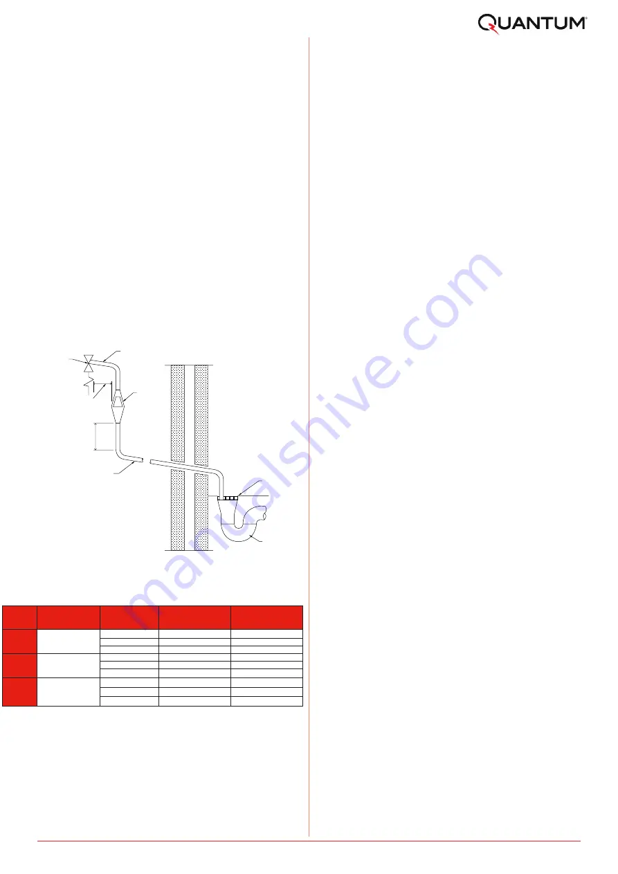
The discharge pipe D2 should be at least one pipe
size larger than the nominal outlet size of the
safety device unless its total equivalent
hydraulic resistance exceeds that of a straight
pipe 9m long, i.e. for discharge pipes between 9m
and 18m the equivalent resistance length should
be at least two sizes larger than the nominal
outlet size of the safety device; between 18 and
27m at least 3 sizes larger than the nominal outlet
size of the safety device; between 18 and 27m at
least 3 sizes larger, and so on; bends must be
taken into account in calculating the flow
resistance. See Figure 1, Table 2 and the worked
example.
Note: An alternative approach for sizing
discharge pipes would be to follow Annex D,
section D.2 of BS 6700:2006 + A1:2009).
Trapped
gully
Fixed
grating
Discharge below
fixed grating
tundish
Metal discharge pipe (D1) from
temperature relief valve to tundish
Metal discharge pipe (D2) from tundish,
with continuous fall. See Table and
worked example
300mm
minimum
600mm maximum
Safety device
(eg. temperature
relief valve)
Figure 1: Typical Discharge Arrangement
Valve Outlet
Size [-]
Minimum size of
discharge pipe before
tundish [mm]
Minimum size of
discharge pipe after
tundish [mm]
Maximum allowed length
of pipe after tundish [m]
Length to be subtracted
for each elbow or bend
[m]
22
9
0.8
28
18
1.0
35
27
1.4
28
9
1.0
35
18
1.4
42
27
1.7
35
9
1.4
42
18
1.7
54
27
2.3
15
22
28
G1/2
G3/4
G1
Table 2: Sizing of copper discharge pipe “D2”
for common temperature relief valve outlet sizes
Pre-Installation
This example is for a G½ temperature relief valve
with a discharge pipe (D2) (as fitted on 125l to
300l cylinders) having 4 No. 22mm elbows and
length of 7m from the tundish to the point of dis-
charge.
From Table 2, the maximum resistance allowed for
a straight length of 22mm copper discharge pipe
(D2) from a G½ temperature relief valve is 9.0m.
Subtract the resistance for 4 No. 22mm elbows at
0.8m each = 3.2m.
Therefore the maximum permitted length equates
to 5.8m, which is less than the actual length of
7m, therefore calculate the next largest size.
Maximum resistance allowed for a straight length
of 28mm copper discharge pipe (D2) from a G½
temperature relief valve equates to 18m.
Subtract the resistance for 4 No. 28m.m elbows at
1.0m each = 4m.
Therefore the maximum permitted length equates
to 14m.
As the actual length is 7m, a 28mm (D2) copper
pipe will be satisfactory.
• Where a single common discharge pipe serves
more than one system, it should be at least
one pipe size larger than the largest individual
discharge pipe (D2) to be connected.
• The discharge pipe should not be connected to
a soil discharge stack unless the soil discharge
stack is capable of safely withstanding temper-
atures of the water discharged, in which case,
it should:
- contain a mechanical seal, which allows
water into the branch pipe without allowing
foul air from the drain to be ventilated
through the tundish.
- there should be a separate branch pipe with
no sanitary appliances connected to it.
- if plastic pipes are used as branch pipes
carrying discharge from a safety device,
they should be either polybutalene (PB) or
cross-linked polyethylene (PE-X) complying
with national standards.
- be continuously marked with a warning that
no sanitary appliances should be connected
to the pipe.
5.4.2
Worked Example
Содержание IOT Series
Страница 12: ...12 Installation Figure 9 Wiring Schematic...
Страница 17: ...17 Spare Parts 9 Spare Parts Figure 13 Replacement Part Numbers for Quantum Electric Range of Cylinders...
Страница 31: ...31 Notes...
Страница 32: ...32 Notes...
Страница 33: ...33 Notes...


