background image

 16 


                        7039-174C 


 August 01, 2016

Discovery I

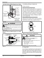
Figure 16.6

Figure 16.1

WARNING!

U

se only noncombustible materials as a decorative tile.

B. Decorative Panel Removal & Installation

Your appliance ships with two different side options, one is a solid 

side panel (

Figure 16.1

) and tile side panel (

Figure 16.3

). There 

are two of each and no left or right side, these can be changed 

at anytime.
The appliances are being shipped with a solid side panel 

securing clip on both sides of the appliance. Please remove 

and discard pins prior to use. (

Figures 16.4

)

Solid Side Panel Removal

1. Remove solid panel from side by lifting up and pulling away 

from appliance (use a flat tool to pry from bottom if needed). 

Figure 16.5

Note: 300 degree F high temp paint can be use to repaint the 

solid side panel only! DO NOT use on the rest of appliance this 

requires 1200 degree F high temp paint.

Tile Panel Installation

1. Remove tile frame from side by lifting up and pulling away 

from appliance. 

Figure 16.5 reference solid side panel re-

moval.

2. Stack non-combustible material tiles in tile frame as shown 

in 

Figure 16.2 

by sliding first tile in, bend tabs on back side, 

then slide last tile in position so that it rests on tabs 

Figure 

16.3

.

3. Reattach tile frame 

Figure 16.6

Tile Dimensional Requirements:

Max Thickness: 5/16” 
Max Length/Width: 11-7/8” square
Min Length/Width: 11-11/16” square

1

Figure 16.5

3

Figure 16.2

Securing 

Clip

Figure 16.4

2

Figure 16.3

Содержание Discovery I Wood Appliance

Страница 1: ...fire If appliance or chimney connector glows you are overfiring Overfir ing will void your warranty Comply with all minimum clearances to combustibles as specified Failure to comply may cause house fi...

Страница 2: ...d 3 D Glass Specifications 3 E Non Combustible Materials 3 F Combustible Materials 3 2 Getting Started 4 A Design and Installation Considerations 4 B Fire Safety 4 C Negative Pressure 5 D Tools And Su...

Страница 3: ...rvice agency or your dealer Hearth Home Technologies WILL NOT warranty appli ances that exhibit evidence of over firing Evidence of over firing includes but is not limited to Warped air tube Deteriora...

Страница 4: ...allation MUST comply with local regional state and national codes and regulations Consult insurance carrier local building fire officials or authorities having jurisdiction about restrictions installa...

Страница 5: ...mbustion appliances and exhaust equipment Ensure furnace and air conditioning return vents are not located in the immediate vicinity of the appliance Avoid installing the appliance near doors walkways...

Страница 6: ...e party responsible for use and operation ATTENTION INSTALLER Follow this Standard Work Checklist This standard work checklist is to be used by the installer in conjunction with not instead of the ins...

Страница 7: ...8 675 3 1 2 89 Figure 7 1 Front View Figure 7 3 Side View 9 1 4 233 24 1 8 613 33 7 8 860 23 5 8 600 13 1 2 343 11 1 2 292 15 381 Figure 7 2 Top View 11 13 16 300 6 11 16 170 3 Dimensions and Clearan...

Страница 8: ...ar floor protection must be provided 18 inches 457mm in front and 8 inches 203mm from the sides and rear of the appliance Figure 8 2 See exception EXCEPTION Non combustible floor protections must exte...

Страница 9: ...4 298 5 3 4 146 23 584 10 1 2 267 7 1 2 191 19 483 43 1092 N A INSTALLATION 90 DEGREE ELBOW OFF TOP OF STOVE THROUGH BACKWALL SINGLE WALL PIPE 17 432 10 254 23 1 2 597 12 305 8 1 2 216 20 508 56 1422...

Страница 10: ...space enclosed by the build ing envelope This helps to produce more draft espe cially during lighting and die down of the fire Penetrate the highest part of the roof This minimizes the affects of win...

Страница 11: ...or when there are other factors that affect flue draft B Chimney Termination Requirements Follow manufacturer s instructions for clearance securing flashing and terminating the chimney Fig 11 1 11 2 M...

Страница 12: ...C S629M Must use components required by the manufacturer for installation Must maintain clearances required by the manufacturer for installation Refer to manufacturers instructions for installation D...

Страница 13: ...ended by chimney connector manu facturer Figure 13 2 Instructions 1 Open inside wall at proper height for the chimney con nector to entry the masonry chimney Figure 13 2 2 Entry hole to masonry chimne...

Страница 14: ...Spacer Wall Band Trim Collar Chimney Connector 1 inch 25mm Air Space to Chimney Section Min Clearance 2 inch 51mm Min Chimney Clearance to Wall Spacer and Combustibles 2 inch 51mm Chimney Section Fig...

Страница 15: ...lation Instructions 1 Remove all materials from packing box 2 Floor Rear Installation Cut a 4 inch 102mm hole in outside wall or floor to accommodate outside air piping Use 4 inch 102mm aluminum metal...

Страница 16: ...ulling away from appliance use a flat tool to pry from bottom if needed Figure 16 5 Note 300 degree F high temp paint can be use to repaint the solid side panel only DO NOT use on the rest of applianc...

Страница 17: ...bracket containing the snap disc and magnet under the bottom left rear corner See Owner s Manual for detailed operating instructions for the blower and snap disc Shock Risk Do NOT remove grounding pro...

Страница 18: ...6 inch 152mm factory built chimney conforming to CAN ULC 629M STANDARD FOR FACTORY BUILT CHIMNEYS 6 Follow the chimney and chimney connector manufacturer s instructions when installing the flue syste...

Страница 19: ...Provide model number and serial number when requesting service parts from your dealer or distributor Stocked at Depot ITEM DESCRIPTION COMMENTS PART NUMBER ACCESSORIES Blower Assembly BK ACC Blower Co...

Страница 20: ...ration DO NOT DISCARD Please contact your Quadra Fire dealer with any questions or concerns For the number of your nearest Quadra Fire dealer log onto www quadrafire com CONTACT INFORMATION This produ...

Отзывы: