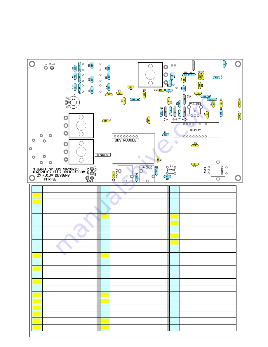
Figure 5:
Capacitors
Since there are a lot of 0.1 ufd caps, these are highlighted in yellow. The rest of the assorted values are in
light blue. We will also install the crystals, highlighted in gray, and are mounted first. Solder a lead clipping
from the hole next to the crystal labeled “G” to the top of the crystal can to ground it. X1 is not grounded.
X1-5 CRYSTALS jumper case to gnd
C21
101 (100 pfd)
C42
102 (.001 ufd) DISK
C1
104 (0.1 ufd)
C22
101 (100 pfd)
C43
103 (.01 ufd) FILM
C2
104 (0.1 ufd)
C23
101 (100 pfd)
C4
4
104 (0.1 ufd)
C3
Electrolytic install later
C24
104 (0.1 ufd)
C45
104 (0.1 ufd)
C4
Electrolytic install later
C25
101 (100 pfd)
C46
104 (0.1 ufd)
C5
Electrolytic install later
C26
101 (100 pfd)
C47
Electrolytic install later
C6
Electrolytic install later
C27
4.7 pfd DISK
C48
104 (0.1 ufd)
C7
471 (470p) DISK
C28
101 (100 pfd)
C49
104 (0.1 ufd)
C8
102 (.001 ufd) DISK
C29
151 (150pfd)
C50
331 (330 pfd)
C9
104 (0.1 ufd)
C30
104 (0.1 ufd)
C51
221 (220 pfd)
C10
471 (470p) DISK
C31
22 pfd DISK
C52
151 (150 pfd)
C11
104 (0.1 ufd)
C32
102 (.001 ufd) DISK
C53
104 (0.1 ufd)
C12
103 (.01 ufd) FILM
C33
Electrolytic install later
C54
681 (680 pfd)
C13
104 (0.1 ufd)
C34
102 (.001 ufd) DISK
C55
561 (560 pfd)
C14
103 (.01 ufd) FILM
C35
101 (100 pfd)
C56
331 (330 pfd)
C15
104 (0.1 ufd)
C36
104 (0.1 ufd)
C57
68 pfd
C16
104 (0.1 ufd)
C37
104 (0.1 ufd)
C58
47 pfd
C17
104 (0.1 ufd)
C38
102 (.001 ufd) DISK
C59
33 pfd
C18
104 (0.1 ufd)
C39
Electrolytic install later
C60
331 (330 pfd)
C19
104 (0.1 ufd)
C40
104 (0.1 ufd)
C61
221 (220 pfd)
C20
104 (0.1 ufd)
C41
104 (0.1 ufd)
C62
151 (150 pfd)
Table 3
Содержание Hendricks PFR-3B
Страница 3: ...Figure 3...
Страница 18: ......
Страница 19: ...Schematics pg1...
Страница 20: ...Schematics pg2...


