


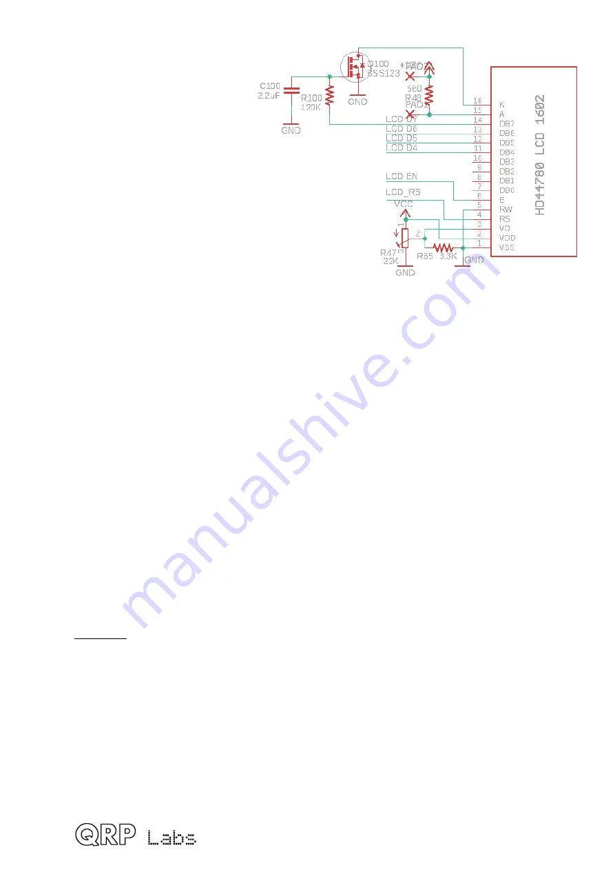
The LCD back-light consumes
about 15mA of current with a
560-ohms series resistor (at 12V
supply). A 270-ohm series
resistor was used in the
QCX/QCX+ and resulted in 30-
35mA current consumption. The
larger resistance value was
chosen here because the
backlight brightness really does
not need to be extreme, and for
portable operations on battery
power, minimizing current
consumption is more important.
The back-light could be
connected directly to the 5V
supply but this would somewhat increase the power dissipation of the 5V voltage regulator.
In order to avoid overheating the regulator, this back-light is powered instead directly from
the +12V rail via R48, a 560-ohm resistor.
A different resistor value could be installed for the LCD backlight series resistor; large pads
are provided on the PCB for this purpose (facilitating easy installation of a standard
through-hole ¼W resistor).
Unlike its predecessors the QCX and QCX+, the QCX-mini transceiver has a means to
switch on or off the backlight under firmware control, via the configuration menu. This is
achieved using LCD data pin 7. Whilst this pin is used for communication from the
microcontroller to the LCD module, this is only a brief data burst lasting a few
microseconds. The rest of the time, the pin can be left in a high or low state, under
processor control.
MOSFET Q100 is used as a switch, in series with the backlight LCD. It is switched ON by
+5V on the gate pin. However, to avoid potential RF noise getting back into the sensitive
QCX-mini receiver circuits, capacitor C100 and resistor R100 form an integrator, the effect
is to filter out the burst of data that occurs when the microcontroller writes to the LCD. The
time constant is 0.26 seconds. Its very slow, plenty slow enough for the data burst to be
totally ignored by the LCD, and therefore no RF interference is generated.
Sidetone
In the early firmware versions of this transceiver, the sidetone was generated by Pulse
Width Modulation using the ATmega328’s Timer1 peripheral. The frequency and volume of
the sidetone were configurable in the software via the configuration menu. In order to
control the volume, the microcontroller adjusted the duty cycle from 50% (maximum
volume) down to under 1% (for minimum volume).
In firmware version > 1.02 and above, the sidetone generation method was changed. The
former method was a simple squarewave, with variable duty cycle, in order to change the
volume. However, this also changed the average level, leading to a DC bias at low volume
levels; on switching from Transmit to Receive (and indeed, vice versa), the DC bias through
the audio chain, being suddenly restored the nominal 2.5V, generated a large click.
QCX-mini assembly Rev 1.05
98
Содержание QCX-mini CW
Страница 15: ...QCX mini assembly Rev 1 05 15...
Страница 16: ...QCX mini assembly Rev 1 05 16...
Страница 17: ...QCX mini assembly Rev 1 05 17...
Страница 19: ...Main board Display board Controls board QCX mini assembly Rev 1 05 19...
Страница 24: ...QCX mini assembly Rev 1 05 24...
Страница 84: ...QCX mini assembly Rev 1 05 84...