40
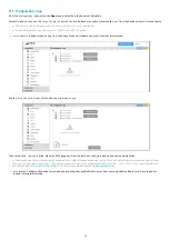
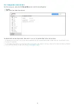
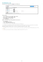
For screen control via AV Command LAN, select the
LAN
option.
With the
button, configure the LAN interface of your device by adding:
the IP address(es) of the screen(s) to drive,
the port to be used (for example, port 1015) for sending AV commands.
☛
Check beforehand in the datasheet that your screen supports AV Command over Ethernet. Using the screen confi guration menu, activate the
support of AV commands over Ethernet on your screen ( for example for a SAMSUNG screen: Menu
Multicontrol
then
MDC C onnection
then select
Ethernet MDC
) .
☛
In order for your display to receive AV commands over Ethernet, mak e sure that your device and display are in the same local network .
Choose the appropriate protocol based on your screen.
☛
F irst check in the datasheet of your screen or audio-video device which AV Command protocol is supported.
☛
If none of the protocols are suitable, you can create your own protocol with the button
or duplicate an existing protocol with the button
and adapt it with your own AV Commands.
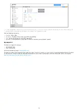
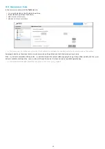
DDC/CI on HDMI-OU T
For AV Command DDC/CI screen control through the H DMI-OUT connector, select the
DDC/CI on HDMI-OUT
option.
◬
Some displays do not support AV Command DDC/CI correctly. If your screen does not exit from standby after activating AVCommand despite
an App that is properly programmed, consider disabling DDC/CI AV Commands for that screen as it probably does not support standby output
AV commands properly.
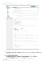
CEC on HDMI-OU T
For screen control by AV Command CEC through the H DMI connector, select the
CEC on HDMI-OUT
option.
◬
Some screen do not correctly support AV commands by CEC. If your screen does not come out of standby after activating AVCommand
despite an App that is properly programmed, consider disabling CEC AV Commands for that screen as it probably does not support standby
output AV commands properly.
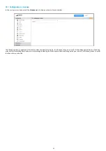
Next, to control your screen with the AV Controls, load and play an appropriate App. It is possible to create your own App that uses the AVCommand
APIs available here:
Содержание 4.13.15 002E
Страница 1: ...U ser manual DMB 400 4 13 15 002E...
Страница 4: ...4 Part I Description and installation...
Страница 7: ...7 1 2 1 Device xture...
Страница 8: ...8 1 2 2 Device dimensions...
Страница 15: ...15 N Function 1 CD 2 RX D 3 TX D 4 DTR 5 GND 6 DSR 7 RTS 8 CTS 9...
Страница 17: ...17...
Страница 19: ...19 Part II Applicative user interface...
Страница 21: ...21 Part III Administration console user interface...
Страница 49: ...49 Part IV Con guration b y script...
Страница 51: ...51 Part V Technical information...
Страница 54: ...54 5 2 Conformities In conformity with the following European directives LVD 2014 35 EU EMC 2014 30 EU...
Страница 55: ...55 Part VI Contacts...
Страница 57: ...57 Part VII Appendix...
Страница 62: ...62 15 16 17...


