8
9
CONNECTING THE CAMERA
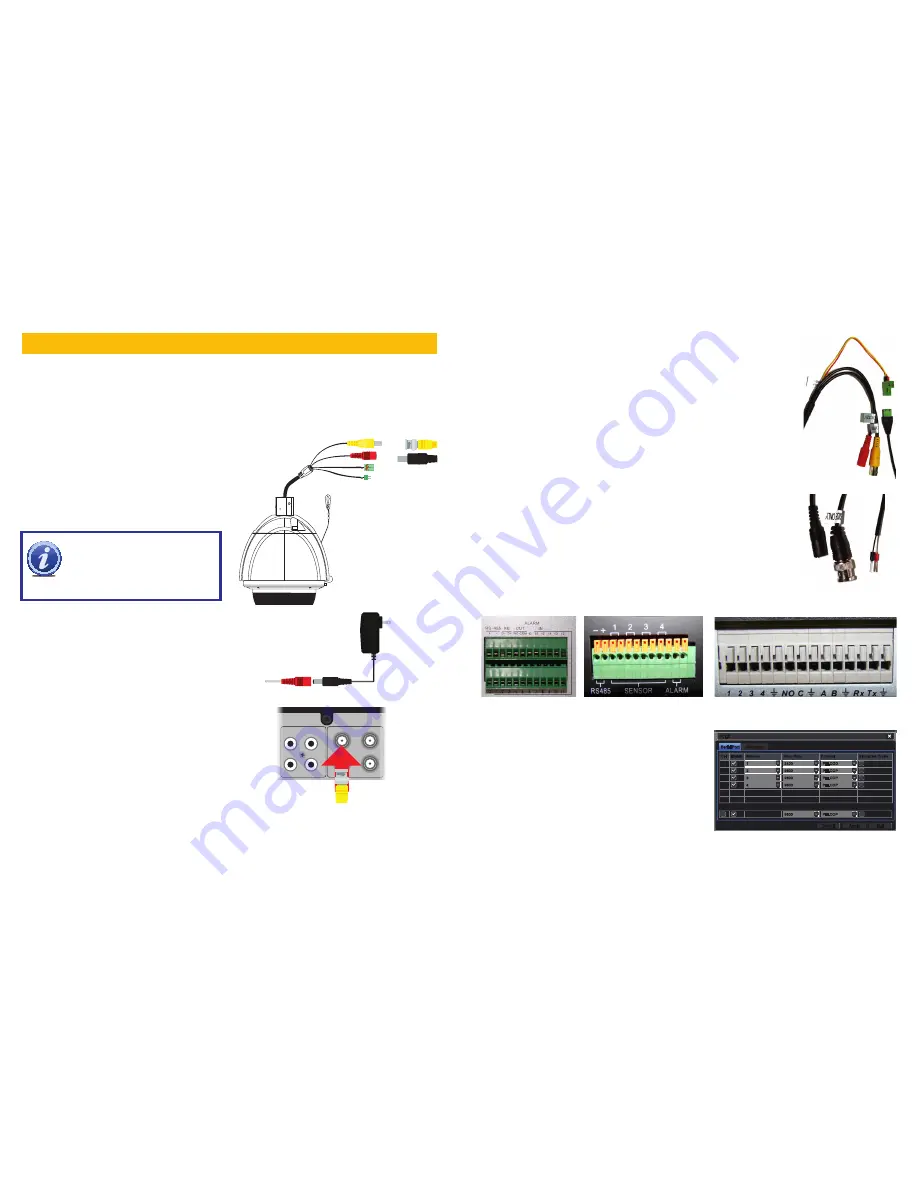
We recommend connecting your camera to your DVR before mounting it as a “dry run” to make
sure everything is operating normally. It is much easier to correct a situation such as a forgotten
lens cap while the camera is on a table than it is when the camera is mounted high up on a wall. If
you will need to change the camera settings such as address, baud rate or communication proto-
col, this would be the time to do so (see
Camera Menu
later in this manual).
POWER AND VIDEO CONNECTION
IMPORTANT!
When connecting
the power and video cable between
the camera and the DVR, the “male”
power end connects to the matching
power lead on the camera.
STEP 1.
Connect the BNC and power leads
from the camera to the matching con-
nectors on the included video/power/
control cable.
STEP 2.
Connect the power lead on the other
end of the video/power cable into the
included
24V 2.2A
power supply.
STEP 3.
Connect the BNC connector on that
same end of the cable to the Video In
port marked
1
on the back of the DVR.
PTZ CONTROL CONNECTION
I
n addition to connecting the power and video leads to the camera, you
must also connect the two control wire leads to the RS485 ports in the
alarm block on the back of the DVR. These blocks can vary in layout
as shown below, but the ports used by your DVR are generally labelled
“RS485”, “PTZ” or “P/Z”.
The RS422 connector will not be used.
As seen in the picture on the upper right, the wire leads from the camera
are two different colors and are labelled. They are also pre-installed into a
block which plugs into a matching receptacle on the extension cable. The
control wire leads at the other end of the extension cable must be inserted
into the ports on the back of the DVR. In the case of the RS485 ports
being marked as positive (+) and negative (-), the wire designated RS485A
(
red tip
) is the positive lead while the wire marked RS485B (
yellow tip
)
is to go into the negative port. PTZ blocks either have small screws to
above each port to secure the wire or require a lock above the port to be
depressed with an object like a small screw driver in order to fully insert the
wire. In the latter, when the lock is released, an internal clamp will keep the
wire firmly secured in the port. If the wire can easily be removed from the
port, then it isn’t secure and you can experience control difficulties until it
is properly attached. Space permitting, multiple PTZ cameras may be con-
nected to the same ports. They will each require a different address.
If you need to mount the camera further than allowed by the included 100’
cable, you will need to get a shielded RG59 video/
power cable that runs the entire didstance and a
pair of 24-gauge wires to connect to the RS485
block. SDI cables should not be extended.
Once you have made your connections, you will
need to make settings on the DVR in order to con-
trol it. You will need to consult your DVR’s manual
for this procedure, but a sample screen (from a
Q-See QT-series DVR) is shown on the right.
Serial Port
Serial Port
Advanced
Advanced
P.T.Z
P.T.Z
Default
Default
Apply
Apply
Exit
Exit
CH Enable Address
Baud Rate
Protocol
Simulative Cruise
1
2
3
4
CH Enable Address
Baud Rate
Protocol
Simulative Cruise
1
2
3
4
All
All
1
1
2
2
3
3
4
4
2400
2400
9600
9600
9600
9600
9600
9600
PELCOD
PELCOD
PELCOP
PELCOP
PELCOP
PELCOP
PELCOP
PELCOP
9600
9600
PELCOP
PELCOP
Some examples of PTZ blocks. One using screws (left) and two using spring-loaded locks.
You can now plug the camera’s power adapter into a surge protector and turn it on. To protect your
investment, we STRONGLY recommended using a surge protector that is UL-1449 rated, for a
clamping voltage of 330 or lower, a Joule rating of at least 400 and a response time of 10 nanosec-
onds or less.
AUDIO IN
VIDEO IN
1
3
2
4
1
3
2
4


