Pyle PLXR2B Скачать руководство пользователя страница 10

www.PyleUSA.com

10

B. CROSSOVER FREQUENCY ADJUSTMENT
     

When setting the crossover frequencies, it is best to use compact discs or


cassette tapes with greater dynamic range. Usually home recorded tapes are


better in this respect than commercially recorded tapes.

System Check

1. Center the tone, balance and fader controls of the source unit (leaving the    
    other controls at their previous positions).
2. Set the volume of the source unit to approximately 2/3 of its maximum output.
3. 

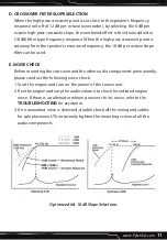
Low-Pass Crossover Frequency Setting: 

Starting from 100 Hz, listen to the   

    bass sound quality, if the bass is “

Boomy

" or soft sounding, select the low-pass  

    frequency to other positions (80/63/50 Hz) until the bass sounds tight and deep.  
    It is all a matter of personal preference. The optimum setting varies from vehicle  
    to vehicle and from individual to individual. Subwoofer crossover frequency
    setting of as low as 80Hz is not uncommon.
4. 

High-Pass Crossover Frequency Setting: 

Starting from 125Hz, adjust the    

    high-pass frequency until you get your desired sound quality. Again, there is no  
    universal optimum setting. It depends on the size and location of the front    
    speakers and also your personal preference.

C. OUTPUT LEVEL ADJUSTMENT

     As in the case of crossover frequency adjustment, when making the output    
     level adjustment it is best to use compact discs or cassette tapes with greater
     dynamic range.
     1. Center the tone, balance and fader controls of the source unit (leaving the
         other controls at their previous positions).
     2. Set the volume of the source unit to approximately 2/3 of its maximum
         output.
     3. With each of the crossover level controls, turn the level up or down until
         distortion develops, then retrace the path until distortion disappears.
     4. Optimum output levels vary with the program source (radio, tape or CD).
         If the optimum output levels for radio differ considerable from those for
         tape/CD, locate the median levels that are best for both program sources.

Содержание PLXR2B

Страница 1: ...2 Way Electronic Crossover Network Independent High Pass Low Pass Output Level Controls ...

Страница 2: ...or What s in the Box 2 Way Electronic Crossover Power Red Wire with 1A Fuse 4 Phillips head Screws Technical Specs Hi Pass Crossover Full 80 100 120 Hz Low Pass Crossover 50 63 80 100 Hz Low Pass 18dB oct 3rd order Butterworth High Pass 6dB or 18dB oct 3rd order Butterworth Distortion 0 05 THD at 1V output level S N Ratio 110dB Output Volt 6V Max Separation 60dB Frequency Response 10 HZ 50 KHZ Vol...

Страница 3: ...hicle battery or other constant 12V source 2 GROUND INPUT CABLE GND To be wired to the vehicle s chassis ground 3 REMOTE TURN ON INPUT CABLE To be connected to the remote control wire or antenna lead of the source unit for remote ON OFF If it is not available connect the orange lead to a switched 12 volt source e g The ignition switch ...

Страница 4: ...lls off at a rate of 12 dB per octave switching the selector to the 6 dB position would produce the ideal 18 dB odd order type phase response 18 dB When the crossover frequency is set away from the speaker s resonant frequency switch the selector to the 18 dB position for ideal 18 dB odd order type phase response 9 HIGH PASS OUTPUT LEVEL CONTROL For adjusting the high pass output signal level 10 L...

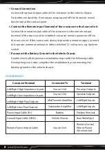
Страница 5: ...www PyleUSA com 5 SYSTEM DIAGRAM Remote Turn On Lead from Head Unit Battery Positive B A B ...

Страница 6: ...s for all the necessary wiring making sure that the wires are easily accessible without dismounting the various components CAUTIONS Routing audio cables and power cables together would invariably cause radiated engine noise in your audio system If possible run audio cables on one side of your car and power cables on the other Never route these wires underneath the vehicle body 1 Check and make sur...

Страница 7: ...protect the wires when they are routed through bare metal holes Note The battery ground should remain DISCONNECTED at all stages of installation E CONNECTIONS 1 Connect the crossover to the Source Unit Connect the outputs of the source unit to the inputs of the crossover either via the low impedance input or the high impedance input 2 Connect the crossover to the Amplifiers Connect the high pass a...

Страница 8: ...2 volt source e g Ignition switch 7 Reconnect the Battery Ground to the Vehicle Chassis Double check all the previous installation steps with the following table If everything is in order complete the installation by reconnecting the battery ground to the vehicle chassis Installation CrossoverTerminal ConnectedTo Terminal Left Right High Impedance Inputs Left Right Low Impedance Inputs Left Right ...

Страница 9: ... the system off immediately Check if connections are made properly refer to sub section titled CONNECTION for details Use a Volt Ohm meter to make sure good chassis ground established for each component that needs to be grounded Check if the power input of all system components are properly connected to 12 volt positive power supply Check if the remote on off terminal of all system components are ...

Страница 10: ...ting of as low as 80Hz is not uncommon 4 High Pass Crossover Frequency Setting Starting from 125Hz adjust the high pass frequency until you get your desired sound quality Again there is no universal optimum setting It depends on the size and location of the front speakers and also your personal preference C OUTPUT LEVEL ADJUSTMENT As in the case of crossover frequency adjustment when making the ou...

Страница 11: ... 18 dB per octave slope filter can be used E NOISE CHECK Before mounting the crossover and the other audio components permanently please conduct the following noise check 1 Start the engine and turn on the power of the source unit 2 Rev the engine and vary the audio volume to check for radiated engine noise If there is an alternator whining noise or tic tic noise refer to the TROUBLESHOOTING for a...

Страница 12: ...speaker short Disconnect speaker wire from amplifier test speaker and wire with a Volt Ohm meter if there is speaker and metal contact slightly enlarge the speaker mounting holes if there is a short in the speaker wiring replace the entire speaker wire or re insulate any exposed wire with electrical tape Check all power wires to see if they are all connected directly to the battery Check all the g...

Страница 13: ...www PyleUSA com 13 ...

Страница 14: ...Questions Issues We are here to help Phone 1 718 535 1800 Email support pyleusa com ...

Отзывы: