Nixie Tube Clock ‘Frank 2 IN-16’
www.pvelectronics.co.uk
- 9 -
4.3
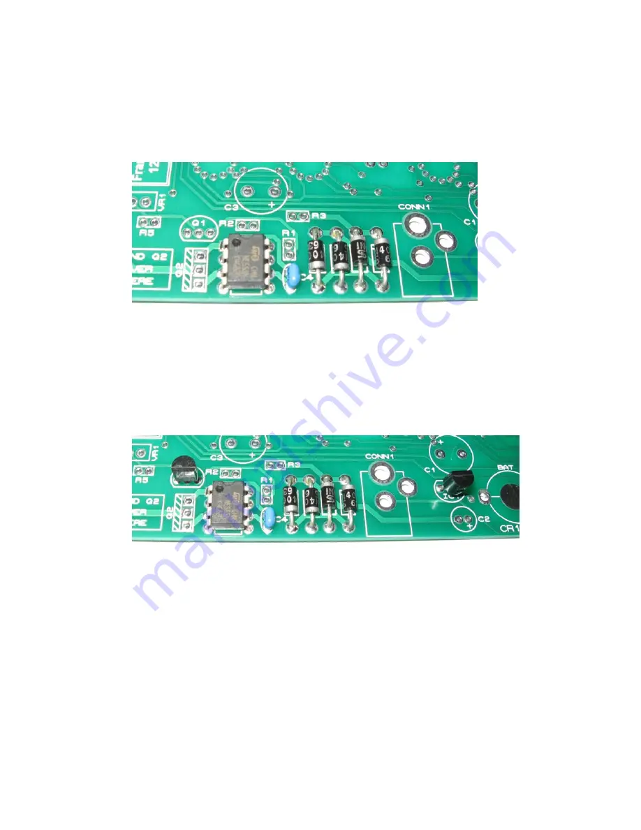
IC2 and C4
IC2 must be oriented correctly. The notch or dot at one end
corresponds to pin 1. This goes into the SQUARE pad. Also place
and solder in C4.
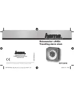
4.4 IC1 and Q1
IC1 and Q1 look very similar, so be careful to identify them
correctly by the white marking on each component. The leads
should not need to be formed, just separated a little. Align the flat
of the body of these components with the marked flat on the PCB.
Push each component into it’s holes until the body is just 2 mm
from the pcb. Solder in and trim the leads.
Figure 5: Q1 (left) and IC1 (right)
Figure 4:
IC2 and C4


