Nixie Clock ‘SN18’
www.pvelectronics.co.uk
- 20 -
4.19
Making up the power input lead
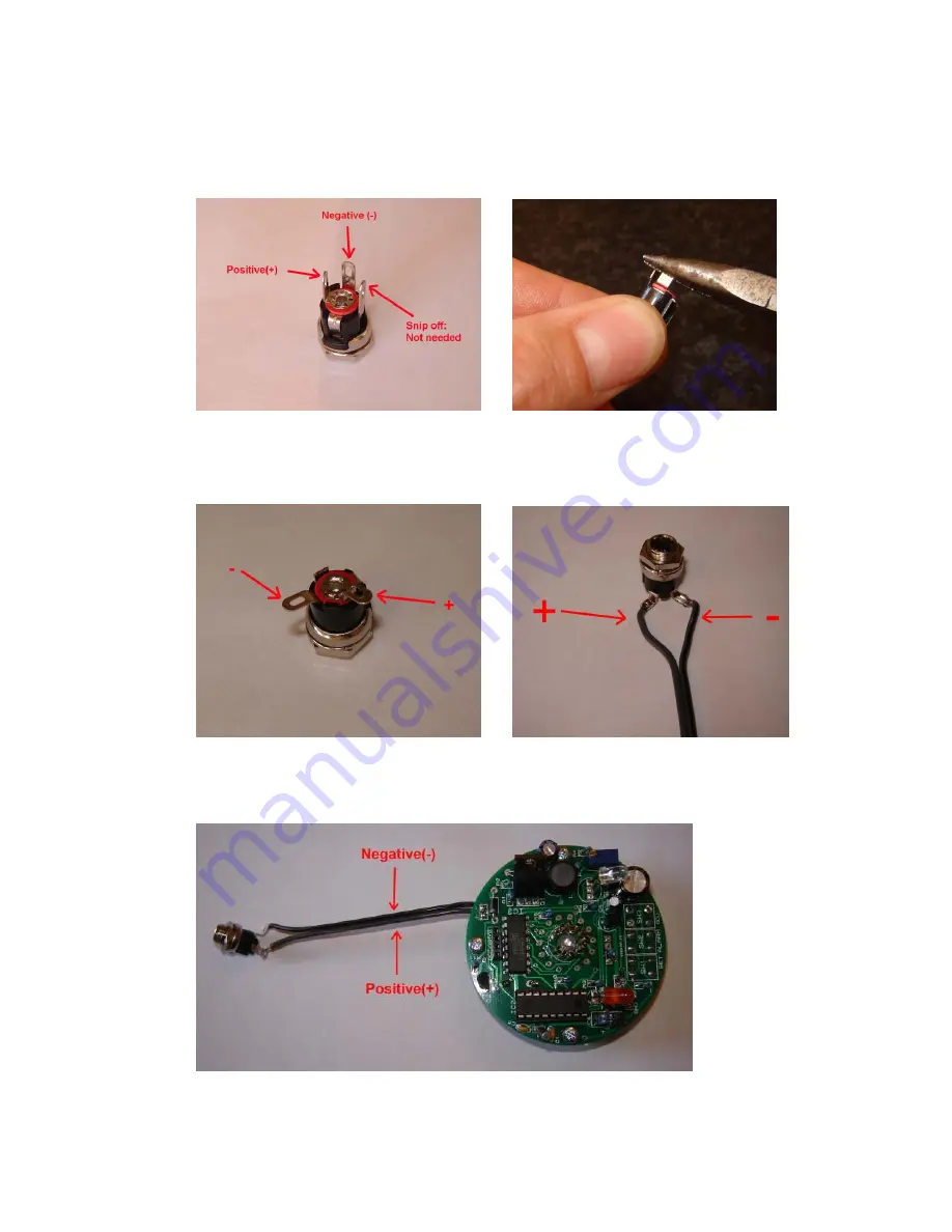
Start by identifying the three connections on the socket as shown
in figure 27, and follow these instructions:
Figure 27: Identify and snip off
Figure 28: Bend the remaining leads
the unwanted lead
as shown. Make a new BEND – don’t
use the existing bend as it will break
Figure 29: Negative and positive pins
Figure 30: Solder on the short cable,
ready for attaching the cable
using the black stripe for the negative
pin
Figure 31:
Solder the
power cable to
the PCB,
connecting the
negative side
to the (–) on
the PCB.


