background image

DESIGNED FOR BINARY BY

PULSE

EIGHT

5

SAFETY PRECAUTION

Please read the instructions before attempting to install or operate this equipment.

Please keep the following in mind as you unpack and install this equipment:

•  The “Designed for BINARY” edition of this matrix operates natively at 12V IR signal, making it compatible with 

Episode  IR  Receivers  and  Flashers.  This  matrix  is  not  compatible  with  5V  IR  receivers  and  flashers  so  extra 

precaution should be taken to avoid irreparable damage to the product Please see IR Receiver and IR Flasher 

under the Compatible Devices section. Always follow basic safety precautions to reduce the risk of fire, electrical 

shock, and injury

• 

To prevent fire or shock hazards, do not expose the unit to rain, or moisture or install this product near water.

•  Never spill liquid of any kind on or into this product

•  Where possible, install the matrix towards the top of the rack to avoid the unit overheating

•  Only use the supplied IEC cable

•  Never push any objects into this product through any openings or empty slots in the unit as you may damage 

parts inside and/or cause an electrical shock

•  Do not allow anything to rest on the power cabling and avoid putting the weight of any kind on it

•  To protect the unit from overheating do not block any vents or openings in the unit housing that provides 

ventilation. Allow sufficient space for air to circulate around the unit.

•  This product is intended for use in a clean (dust-free) residential environment

Ventilation

It’s important to keep the product well ventilated when installing this Pulse-Eight matrix

Any electronic equipment will generate heat A well-ventilated area helps to disperse the heat If placed in a poorly 

ventilated area, your equipment may heat up and cause irreparable damage to the circuitries 

Allowing systems to run for prolonged periods under high temperatures will break down circuitry and electrical 

component It also applies if the device is left in the path of direct sunlight or near any heat source

Dust tends to accumulate and will disrupt the fan and electronics system Dust particles contain various 

compositions like water, oil, and other minerals or chemicals Having them in your electronic device can sometimes 

cause a signal error or degradation to the internal chips and circuitries Because we cannot accurately predict 

how or when they can affect your device, we highly recommend that you keep Pulse-Eight products not only in a 

well-ventilated area but also as clean as possible

In some cases, insects or reptiles can make nests near or inside the electronic casing Whilst we design our 

products to maximize the protection of internal electronics, please be aware that insects and reptiles can be 

drawn to these types of habitats In the unlikely event, this does happen, this will lead to poor ventilation inside 

the unit, and it will be unable to disperse heat effectively.

Finally, whenever possible, do not stack audio and video matrixes together Leave enough space in between each 

unit in order to provide good airflow.

FCC Warning

This equipment has been tested and found to comply with the limits for a Class B digital device, pursuant to part 15 of the FCC Rules 
These limits are designed to provide reasonable protection against harmful interference in a residential installation This equipment 
generates, uses and can radiate radio frequency energy and, if not installed and used in accordance with the instructions, may cause 
harmful interference to radio communications However, there is no guarantee that interference will not occur in a particular installation 
If this equipment does cause harmful interference to radio or television reception, which can be determined by turning the equipment 

off and on, the user is encouraged to try to correct the interference by one or more of the following measures:

•  Reorient or relocate the receiving antenna
•  Increase the separation between the equipment and receiver
• 

Connect the equipment into an outlet on a circuit different from that to which the receiver is connected.

•  Consult the dealer or an experienced radio/TV technician for help

Содержание Binary neo XMR

Страница 1: ......

Страница 2: ...y Precaution 5 Panel Descriptions 6 Compatible Device 7 Installation 9 IR Receiver And Transmitter Ports 13 Wiring Guidelines 14 Neo Web Interface 15 Monitoring Portal 26 EDID Management 30 IR Blastin...

Страница 3: ...with the option of Optical and Digital Coax The neo XMR Binary goes the distance supporting up to full 4K 60 4 4 4 8bit or 4K 60 4 2 2 12bit up to 100 meters 330 feet With audio breakout Dolby Digital...

Страница 4: ...support IR Inputs to Room Yes IR Outputs to Source Yes IR Receivers Supports Episode IR Receivers not included IR Flashers Supports Episode IR Flashers not included Ethernet Ports 1 x RJ45 control and...

Страница 5: ...e path of direct sunlight or near any heat source Dust tends to accumulate and will disrupt the fan and electronics system Dust particles contain various compositions like water oil and other minerals...

Страница 6: ...k connection RED No network cable is connected AMBER Flashing It discovers the IP address AMBER Solid The network has the IP but cannot ping the router GREEN Flashing The network cannot reach the inte...

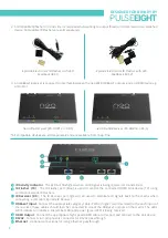
Страница 7: ...devices Power Connector is used with the supplied power cord to connect the power HDBaseT Outputs Connect the appropriate Cat5e or higher grade cable to each output These cables should then be connect...

Страница 8: ...is being received or transmitted IR Flasher TX The IR Flasher port blue is used to control the connected HDMI Sink device TV using compliant Episode IR Flashers IR Receiver RX The IR Receiver port gr...

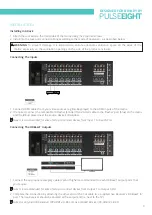
Страница 9: ...tible IR Flasher Emitter Transmitter cable to the Flasher port blue on the matrix and the IR bud placed over the source device s IR window 1 Connect the appropriate category cable Cat6 or higher recom...

Страница 10: ...and 8 connect sink devices e g TVs directly via high speed HDMI cables The neo XMR features 4 zones of independent audio inputs Connect your audio source device directly to either the digital coax or...

Страница 11: ...nded to match the video routing There are two sub modes of operation for each output zone Passive mode is a fixed line level output It is recommended when connecting to an amplifier with its own volum...

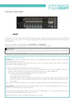
Страница 12: ...ug into the AC mains 2 Turn ON the power switch 3 As it powers ON the front panel LEDs System Health Network Cloud will illuminate momentarily before it begins its initialization sequence Note The ini...

Страница 13: ...port according to the video routing to that HDBT output e g if the matrix is routing video from HDMI In 2 on to HDBT out 5 then the any IR signal received by the neo Receiver attached to HDBT port 5...

Страница 14: ...urce Mode Sink Mode This is an example of a wiring diagram of the neo XMR Binary with a dedicated audio matrix switch e g ProAudio1632 and an amplifier e g ProAmp8 This is an example of a wiring diagr...

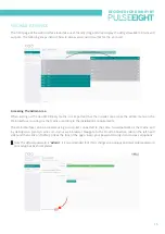
Страница 15: ...the admin menu on the Web Interface to configure the matrix according to the installation s requirements The Web Interface can be accessed using a computer connected to the same router network as the...

Страница 16: ...onitor all of your Pulse Eight installations remotely in one place For more information refer to the Accessing the Monitoring Portal section in this manual Note If you do not already have an Installer...

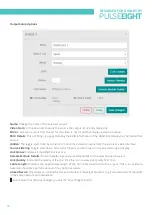
Страница 17: ...Management section of this manual for more information EDID Details This will bring up a page detailing the current EDID information for the selected Input Enable IR 12V Turn on will enable a 12V DC v...

Страница 18: ...ltering Toggle switches to select which inputs can be routed to the selected output display Link Status Indicates if the HDBT link is active Remote Module Details This will display a popup providing d...

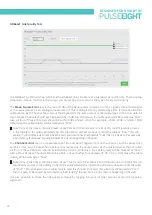
Страница 19: ...speci c areas of your installation to identify potential faults The IR Noise Test will check to see if any unwanted IR noise is being received over a sustained period of time for each port Failing th...

Страница 20: ...in the Cat cable All four of these Channels should be below the 40 line Otherwise the cable quality will be marked as Poor Also all four of these Channels should be within 3 of each other for example...

Страница 21: ...ol section for further details It is possible to add the neo XMR matrix to your Alexa smart home setup in order to control the attached Sink and Sources using voice commands 1 Install the neo Alexa sk...

Страница 22: ...Web based control does require a persistent network connection Discovery Tool You can download a discovery tool from your monitoring portal at http monitoring pulse eight com this program will run on...

Страница 23: ...remote e g the Guide button then enabling this function allows you to use a combination of keys on the remote instead to achieve the missing function IR Control IR Activity A useful test for IR activi...

Страница 24: ...reo output Choose Active to manage the volume and delay of the stereo output and enable Audio Return Channel ARC When Active Mode is selected the following options will appear Delay A slider to adjust...

Страница 25: ...re revision and current firmware version installed You may be asked for this information if you request support It also details the firmware versions for the HDBaseT components transmitters and connec...

Страница 26: ...l display your details including your Installer ID Under the My Installs tab you can add projects and assign your installed systems in order to easily access and monitor certain installations To creat...

Страница 27: ...BINARY BY PULSEEIGHT 27 Once created you will then be able to assign systems to the install by clicking the Add button in the Products section This will then bring up a page with a dropdown menu to se...

Страница 28: ...re Version Current Uptime System Status Inputs System Status Outputs External Network Details Local Network Con guration System Commands Reboot Function My Products Under the My Products tab all your...

Страница 29: ...on and detail any updates available for the system There is also a toggle switch to turn on Hot x Updates whereby updates are delivered automatically to the system Installation Report displays all cru...

Страница 30: ...EDID to only support the resolutions supported by all the displays connected to the outputs Clone Display Copies the same EDID as TV attached to the output X HDR UltraHD 4K 1080p 720p It sets the EDID...

Страница 31: ...to a maximum of 4K that is then distributed to all connected displays Any legacy display supporting up to 1080p only will likely display an error or no picture When this occurs it is possible to use a...

Страница 32: ...driver can easily be configured to control and manage all video sources and displays flawlessly from your Control4 system through the neo XMR matrix For more information please refer to the neo XMR Bi...

Страница 33: ...e 1 Here is the mapping and wiring diagram of an example setup 2 To use the Linked Device feature make sure to connect to the correct output Here is an example of the setup a S PDIF connector is conne...

Страница 34: ...4 4 Once the Output window is up select the ProAmp8 on the Linked Device section and select Input 9 as re ected as the Input on the ProAmp8 3 Next on the neo XMR web UI go to Video Routing and under t...

Страница 35: ...Then click the Con guration tab and click on the icon to check if it is Output 2 Make sure they are connected to the neo XMR correct output which is Output 2 in this case 6 Once both sides can see th...

Страница 36: ...ed RJ45 connectors or excess cable lengths Ensure your cable is correctly wired to 568B standards Pink or off colour picture This could be caused by an invalid EDID or the source device failing to rea...

Страница 37: ...way from direct sunlight Halogen lighting and plasma screens may also interfere with IR signals Infrared Not Functioning 1 Make sure to use the compatible IR asher receiver for this video matrix 2 Che...

Страница 38: ...J45 Right OFF No Video GREEN Blink Video Present No HDCP GREEN Solid Video Present HDCP HDBT Output OFF No HDBT RX connected GREEN HDBT RX connected PoH enabled HDMI Input OFF No Signal GREEN HDMI 5V...

Страница 39: ...s with DSC 4 4 4 8 Bit No Yes 10 Bit Yes Yes with DSC 12 Bit Yes Yes with DSC 50 60 4 2 0 8 Bit No Yes 10 Bit Yes Yes with DSC 12 Bit Yes Yes with DSC 4 2 2 8 Bit No Yes with DSC 10 Bit Yes Yes with D...

Страница 40: ...DESIGNED FOR BINARY BY PULSEEIGHT 40 NOTES...

Отзывы: