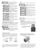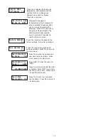
R
C
W1/OB
W2/E
Y
G
ZONE1 TS
TA
T
R
C
W1/OB
W2/E
Y
G
ZONE1 TS
TA
T
Zone 2 or 3 Thermostat
Heat/Cool
24VAC
R
C
W1/OB
W2/E
Y1
Y2
G
Zoning Panel
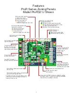
Wiring Zone Thermostats
Heat/Cool Thermostats
Heat Pump Thermostats with Auxiliary Heating
Gas/electric systems using Heat/Cool thermostats. Wiring for
these thermostats is shown below.
Heat/Cool thermostats can be used in all zones. A heat pump
thermostat can be used in Zone1 with heat pump equipment to
control emergency heating. The type of thermostat can be
selected using the PDMi3.
6.
A heat pump thermostat should be used in Zone1 when heat
pump equipment is selected. Wiring of a heat pump zone
thermostat is shown below.
R
C
W1
Y1
G
ZONE2 TST
A
T
R
C
W
Y
G
R
C
W1
Y1
G
Zoning Panel
Thermostat
R
C
Y or Y1
G
Zoning Panel
R
C
24VAC
24VAC Common
Cooling, Stage1
Indoor Fan
Y
G
Terminal Function
W1
Stage1 Heating
W
Zoning Panel
Zone 1 Thermostat
Heat/Cool
24VAC
Thermostat
R
C
Y or Y1
G
Zoning Panel
R
C
24VAC
24VAC Common
Cooling, Stage1
Indoor Fan
Y
G
Terminal Function
W1/OB
Stage1 Heating
W1/OB
Inside
Day
Th
MODE
MENU
FAN
SYSTEM
Schedule
Auto
Heat
Heat
Set To
AM
Inside
Day
Th
MODE
MENU
FAN
SYSTEM
Schedule
Auto
Heat
Heat
Set To
AM
Inside
Day
Th
MODE
MENU
FAN
SYSTEM
Schedule
Auto
Heat
Heat
Set To
AM
4
ZONE
D
AMPER
3
Installing Dampers
Wiring Dampers
One or more dampers can be used to define a zone. Dampers
should be installed in the duct or ducts and sealed to insure no
air leakage. Shown below is the ProR80J-XX damper.
The dampers are connected to the zoning panel with the cables
provided with each damper.
4.
5.
Zoning Panel
25-foot RJ12 cable
supplied with damper.
Plug damper cable into the
Zone Damper connector on
the zoning panel.
Daisy chained dampers
when more than one
damper required to
configure a zone.
AIRFLOW
Model ProR80J-008
ProZone
In
te
lli
ge
nt
Zo
ni
ng
IN
OUT
Model A80-MJ
Modulating Position
Damper Actuator
24VAC, 2.2VA
Made in USA
ProZone
IN
OUT
Model A80-MJ
Modulating Position
Damper Actuator
24VAC, 2.2VA
Made in USA
ProZone


