Chapter 2 Hardware Configuration
PA-5822 USER MANUAL
Page: 2-3
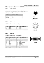
2.2
Function Buttons and I/O Ports
2.2.1
Power Button
To turn on the system, press the power button on the side
of the system briefly.
ACTION
ASSIGNMENT
Click
0V
Release
+3.3V
2.2.2
DC-IN Port
DC-IN:
DC Power-In Port (rear IO)
PIN ASSIGNMENT
PIN ASSIGNMENT
1
GND
3
+24V
2
GND
4
+24V
2.2.3
VGA Port
VGA:
VGA Port, D-Sub 15-pin (rear IO)
PIN ASSIGNMENT
PIN ASSIGNMENT
1
RED
9
+5V
2
GREEN
10
GND
3
BLUE
11
NC
4
NC
12
DDCA DATA
5
GND
13
HSYNC
6
GND
14
VSYNC
7
GND
15
DDCA CLK
8
GND
-
-
DC-IN
Power
Button
VGA
1
5
6
10
11
15
Содержание PA-5822 M1
Страница 10: ...vii Figure 3 26 Boot Menu Screen 3 52 Figure 3 27 Save Exit Menu Screen 3 54...
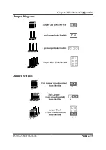
Страница 32: ...Chapter 2 Hardware Configuration PA 5822 USER MANUAL Page 2 11 Jumper Diagrams Jumper Settings...
Страница 119: ...Appendix A System Diagrams PA 5822 SERIES USER MANUAL Page A 2 HDD Tray Disassembly...
Страница 120: ...Appendix A System Diagrams PA 5822 SERIES USER MANUAL Page A 3 MSR module Assembly...


