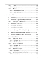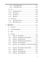
vii
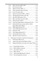
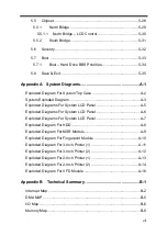
Chipset .................................................................................... 5-28
North Bridge .................................................................... 5-29
– LCD Control ......................................... 5-30
South Bridge .................................................................... 5-31
Security ................................................................................... 5-32
Boot ......................................................................................... 5-33
– Hard Drive BBS Priorities ..................................... 5-34
Save & Exit .............................................................................. 5-35
Appendix A System Diagrams .................................................... A-1
Exploded Diagram For System Top Case ................................................A-2
System Exploded Diagram .......................................................................A-3
Exploded Diagrams For System LCD Panel ............................................A-5
Exploded Diagrams For System LCD Panel ............................................A-6
Exploded Diagrams For System LCD Panel ............................................A-7
Exploded Diagram For HDD .....................................................................A-8
Exploded Diagram For MSR Module ........................................................A-9
Exploded Diagram For Fingerprint Module ............................................A-10
Exploded Diagram For 3-Inch Printer (1) ............................................... A-11
Exploded Diagram For 3-Inch Printer (2) ...............................................A-12
Exploded Diagram For 2-Inch Printer (1) ...............................................A-13
Exploded Diagram For 2-Inch Printer (2) ...............................................A-14
Exploded Diagram For VFD Module ......................................................A-16
Appendix B Technical Summary ................................................ B-1
Содержание PA-3222
Страница 1: ...USER MANUAL PA 3222 10 1 POS Terminal Powered by Intel Celeron J1900 Quad Core PA 3222 M1...
Страница 11: ...viii Configuring WatchDog Timer B 10 Flash BIOS Update B 13...
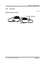
Страница 24: ...Chapter 2 Getting Started PA 3222 SERIES USER MANUAL Page 2 10 2 3 6 Side View 147 75...
Страница 26: ...Chapter 2 Getting Started PA 3222 SERIES USER MANUAL Page 2 12 2 4 3 Top View...
Страница 37: ...Chapter 3 Hardware Configuration PA 3222 SERIES USER MANUAL Page 3 7 Jumper diagrams Jumper settings...
Страница 163: ...Chapter 4 Software Utilities PA 3222 SERIES USER MANUAL Page 4 78...
Страница 173: ...Chapter 4 Software Utilities PA 3222 SERIES USER MANUAL Page 4 88 e Example 3 PROMAG MSR PART NO HID mode...
Страница 221: ...Appendix A System Diagrams PA 3222 SERIES USER MANUAL Page A 4...
Страница 227: ...Appendix A System Diagrams PA 3222 SERIES USER MANUAL Page A 10 Exploded Diagram For Fingerprint Module 150 149 147 148...
Страница 232: ...Appendix A System Diagrams PA 3222 SERIES USER MANUAL Page A 15 With Paper Holder Without Paper Holder 03...
Страница 247: ...Appendix B Technical Summary PA 3222 SERIES USER MANUAL Page B 14...


