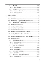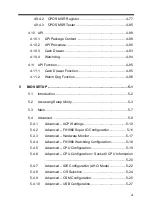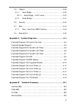
iii
USB Connectors (USB6, USB7) ..................................... 3-18
LED Connector (LED1) ................................................... 3-19
Speaker Connector (SPK1_1) ......................................... 3-19
Power Connectors (DC12V, DC24V) .............................. 3-20
Inverter Connector (INV1) ............................................... 3-21
Reserved Connectors (SPK2_1, GPIO1) ........................ 3-21
Panel Resolution Selection (JP5, JP6)............................ 3-22
Mini PCIE USB Selection (JP13) ..................................... 3-22
MSR / Card Reader Connector (PS2) ............................. 3-23
LVDS Connector (LVDS1) ............................................... 3-24
Touch Panel Signal Interface Selection (JP8, JP9) ......... 3-25
SATA & SATA Power Connector (SATA1, SATA2,
SATA_PWR1, SATA_PWR2) ........................................... 3-26
BIOS Update Selection (JP1) .......................................... 3-27
Clear CMOS Data Selection (JP2) .................................. 3-27
LVDS Link (JP16) ............................................................ 3-28
LVDS Voltage Selection (JP17) ....................................... 3-28
Panel Enable Selection (JP20) ........................................ 3-29
Mini-PCIe Connector (M_PCI_E1) .................................. 3-29
Printer Board Component Locations & Pin Assignment ......... 3-30
Printer Board: PDAC-3100 .............................................. 3-30
Jumper & Connector Quick Reference Table .................. 3-31
Setting Printer Board Connectors and Jumpers: PDAC-3100
......................................................................................... 3-32
Power Supply Connector ............................................. 3-32
RS-232 Interface Connector ........................................ 3-32
Auto-Cutter Connector ................................................. 3-33
USB Connector ............................................................ 3-33
Thermal Head/Motor/Sensor Connector ...................... 3-34
Terminal Assignment Connector .................................. 3-36
Содержание PA-3222
Страница 1: ...USER MANUAL PA 3222 10 1 POS Terminal Powered by Intel Celeron J1900 Quad Core PA 3222 M1...
Страница 11: ...viii Configuring WatchDog Timer B 10 Flash BIOS Update B 13...
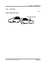
Страница 24: ...Chapter 2 Getting Started PA 3222 SERIES USER MANUAL Page 2 10 2 3 6 Side View 147 75...
Страница 26: ...Chapter 2 Getting Started PA 3222 SERIES USER MANUAL Page 2 12 2 4 3 Top View...
Страница 37: ...Chapter 3 Hardware Configuration PA 3222 SERIES USER MANUAL Page 3 7 Jumper diagrams Jumper settings...
Страница 163: ...Chapter 4 Software Utilities PA 3222 SERIES USER MANUAL Page 4 78...
Страница 173: ...Chapter 4 Software Utilities PA 3222 SERIES USER MANUAL Page 4 88 e Example 3 PROMAG MSR PART NO HID mode...
Страница 221: ...Appendix A System Diagrams PA 3222 SERIES USER MANUAL Page A 4...
Страница 227: ...Appendix A System Diagrams PA 3222 SERIES USER MANUAL Page A 10 Exploded Diagram For Fingerprint Module 150 149 147 148...
Страница 232: ...Appendix A System Diagrams PA 3222 SERIES USER MANUAL Page A 15 With Paper Holder Without Paper Holder 03...
Страница 247: ...Appendix B Technical Summary PA 3222 SERIES USER MANUAL Page B 14...


