RDM0012 Issue 1 AA
Page 21 of 35 © Protec Fire Detection PLC 2017
4.4
Insulation and Continuity Testing of Cabling
Whilst the front panel is removed and the loop continuity switch is in the commissioning position,
cable insulation and continuity tests may be performed if required.
Tests should be carried out using a 500V DC insulation tester (‘Megger’). If tests are performed the
insulation readings between each cable core, and each cable core and earth must be greater than
10MΩ.
The front panel must not be connected when high voltage insulation tests are being
performed on the cabling. The cabling must be completely discharged prior to connection
to the front panel. Equipment connected to the cabling during testing will be damaged
by the high voltages used, invalidating any warranty.
4.5
Connecting the Front Panel
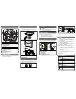
Connect the ribbon cable to the terminal board. The terminal board has an integral cable restraint,
push the ribbon gently into the slot on the board as show below. The ribbon should curve neatly
beneath the terminal board. Reset the loop continuity switch on the terminal board back to the
running position. Failing to do so may compromise loop fault detection, the front panel will report this
as an error.
Reset the loop continuity switch on
the terminal board back to the
running position.


