3
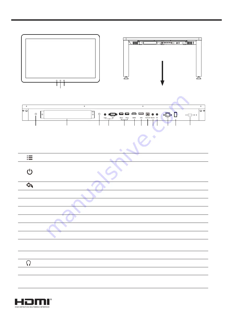
IDENTIFICATION OF CONTROLS
1
Press the button to show the
Navigationt Bar
.
2
Press to switch the screen on or off.
When the screen is turned on, press the button to show the
Navigationt Bar
.
Press the button for about 2 seconds and the screen will go into stand-by
mode.
3
Return to previous screen.
4
WiFi
WiFi antenna
for OPS.
5
OPS module slot
Insert an OPS module (Optional)
6
PC IN
Connect the video/audio of a computer to these ports.
7
USB
Connect USB devices to these ports.
8
HDMI INPUT
Connect an HDMI or DVI device to this jack.
9
DP(DisplayPort) INPUT
Connect an external device to DP out jack.
10
TOUCH OUT
Output for external devices connected to PCx, HDMIx or DP ports, which
support touch systems.
11
RS-232C
For remote control, service and other uses.
12
Connect headphones to this jack. The screen is the current audio output.
13
LAN
Connects the external network or the router.
14
Power Switch
Push ( I ) to connect the power, push (O) to cut off the power.
Note:
Don’t cover the power switch.
The terms HDMI and HDMI High-Definition Multimedia Interface, and the HDMI Logo are
trademarks or registered trademarks of HDMI Licensing LLC in the United States and other
countries.
1
Remote Sensor
2
3
4
4
6
7
8 9
10
1112
13 14
5


