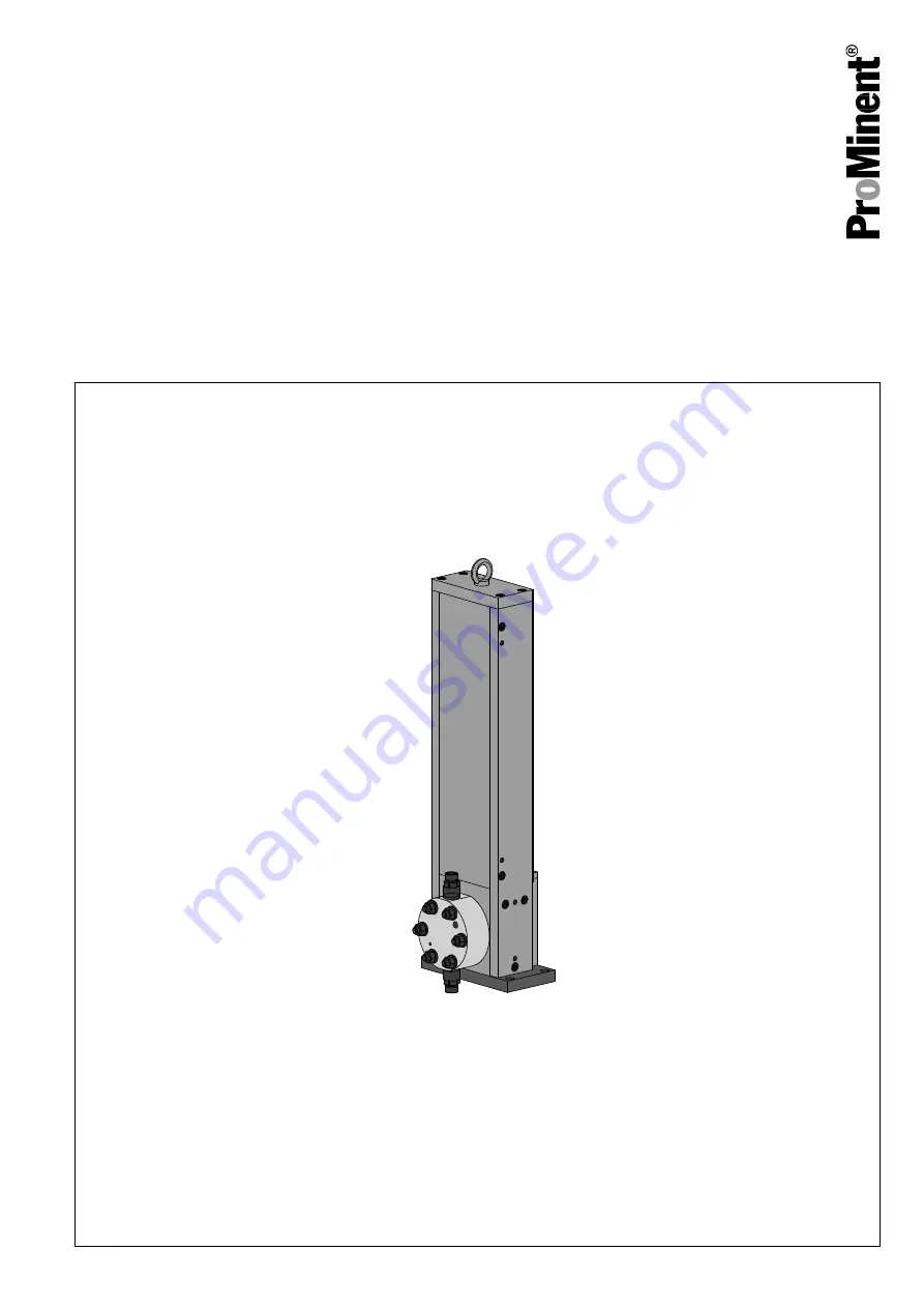
ProMinent EMFa Скачать руководство пользователя страница 1

Metering pump

Evolution mikro, EMFa / EMHa

Operating instructions

These operating instructions form part of combined documentation and, as such, are only valid if used in conjunction with

the other documents.
Target group: trained, qualified personnel, unless otherwise required.

EN

Original operating instructions (2006/42/EC)

981089

Version: BA ORL 012 09/21 EN

Please carefully read these operating instructions before use. · Do not discard.

The operator shall be liable for any damage caused by installation or operating errors.

The latest version of the operating instructions are available on our homepage.

Содержание EMFa

Страница 1: ...ments Target group trained qualified personnel unless otherwise required EN Original operating instructions 2006 42 EC 981089 Version BA ORL 012 09 21 EN Please carefully read these operating instruct...

Страница 2: ...o the precise designation of suppliers components in the Technical Data chapter for ease of finding the relevant information These operating instructions conform to current EU regulations applicable a...

Страница 3: ...tallation 24 5 1 Installation hydraulic 24 5 1 1 Basic installation notes 26 5 2 Installation electrical 26 5 2 1 Motor controller cables 26 5 2 2 Controller 27 5 2 3 Diaphragm monitor optional 27 5 2...

Страница 4: ...dity 63 11 7 3 Installation height 64 11 8 Housing degree of protection 64 11 9 Diaphragm monitoring sensor 64 11 10 Safety relief valve Evolution mikro 65 11 11 Sound pressure level of HA2a HA3a 65 1...

Страница 5: ...rive means that the pump does not need a gearbox The piston 2 of the liquid end is connected directly to the motor M The pump s separate electronic controller can vary the stroke and stroke rate witho...

Страница 6: ...rotection in parked position 2 Vent screw 3 Motor controller connecting cable 4 Controller C1100 1150 5 Motor housing 6 Oil inspection window 7 Pressure relief valve 8 Diaphragm rupture indicator 9 Bl...

Страница 7: ...100 1150 Standard control See identity code 1 2 2 Scope of delivery of the Evolution mikro ATEX A3429 Pump Cable Controller ATEX Zone 1 No ATEX By the customer Version A B and C Delivery limit Pt1000...

Страница 8: ...160 strokes min 180 180 strokes min 200 200 strokes min Pressure stage A 10 bar D 25 bar E 40 bar H 64 bar J 80 bar K 100 bar N 160 bar P 250 bar Dosing head material S2 Standard stainless steel 1 440...

Страница 9: ...troke length 4 Analogue 2 parameters 5 Analogue 3 parameters 6 Analogue fieldbus Ambient temperature 0 20 C 40 C 1 10 C 50 C 3 10 C 55 C 4 0 C 60 C Paintwork pump housing 0A unpainted aluminium 0S unp...

Страница 10: ...2 CE EAC 3 CE EAC ATEX 4 CE UKCA 5 CE UKCA ATEX Documentation DE German EN English FR French ES Spanish RU Russian Measuring unit 0 bar l h 1 psi gph 2 kPa l h other languages on request Functional d...

Страница 11: ...on with PTFE diaphragm S Standard P PTFE diaphragm EMHa Evolution mikro with metal dia phragm A ATEX 240 Motor size D Double diaphragm E Single diaphragm AL Aluminium housing 6 6 mm piston SS Stainles...

Страница 12: ...Fatal or very serious injuries Measure to be taken to avoid this danger Denotes a possibly hazardous situation If the situa tion is disregarded it could result in fatal or very serious injuries CAUTI...

Страница 13: ...asks assigned to him and recognize possible hazards based on his training knowledge and experience as well as knowledge of pertinent regulations A trained qualified employee must be able to perform th...

Страница 14: ...rating instructions n Observe the general limitations with regard to viscosity limits chem ical resistance and density see also the ProMinent Resistance List in the Product Catalogue or at www promine...

Страница 15: ...stations affected WARNING Ignition hazard by exothermic reaction Certain oils from the intermediate diaphragm chamber can react exothermically and become hot with certain feed chemicals Assess the req...

Страница 16: ...ct with the chemical Take into account the resistance of the wetted mate rials and the ProMinent Resistance List when selecting the feed chemical see the ProMinent Product Catalogue or visit ProMinent...

Страница 17: ...sparks Only perform repair and maintenance work assembly disassembly in a clean room without an explosive atmos phere Electrical sources of ignition The installation dismantling placement of electric...

Страница 18: ...ible at all times Danger of tipping over Magnetic field Hot surface 2 8 Sound pressure level Sound pressure level LpA 70 dB according to EN ISO 20361 at maximum stroke length maximum stroke rate maxim...

Страница 19: ...nd on our homepage WARNING High centre of gravity The unsecured pump can easily topple over Only transport the pump horizontally WARNING The ring bolt can break off If the pump is connected to other c...

Страница 20: ...ar ventilation 3 Store the pump in a dry sealed place in line with the prescribed ambient conditions refer to the chapter entitled Technical data 1 Check whether the transport protection is screwed in...

Страница 21: ...Specification Value Maximum air humidity 95 relative humidity non condensing according to DIN IEC 60068 2 30 Storage transport and unpacking 21...

Страница 22: ...such as the oil inspec tion window are easily accessible 2 Make sure that there is enough space to carry out an oil change or bearing change vent screws post suction valve oil trough 3 Ensure there i...

Страница 23: ...that no vibrations can occur 1 Take the dimensions of the fastening holes from the appropriate dimensional or data sheets 2 Use 3 suitable screws to fix the hydraulic block pump base to the supportin...

Страница 24: ...orkstations affected WARNING Warning of feed chemical reactions to water Feed chemicals that should not come into contact with water may react to residual water in the liquid end that may originate fr...

Страница 25: ...0 120 Fz N 60 120 Mx Nm 3 6 My Nm 3 6 Mz Nm 0 0 Before starting up replace the sealing stopper in the dosing head with the selected diaphragm rupture sensor The necessary back pressure for the reliabl...

Страница 26: ...electrical technician Chapter 2 2 User qualification on page 13 WARNING With ATEX pumps perform all work in the absence of an explosive atmosphere What requires electrical installation n Motor control...

Страница 27: ...documenta tion Download see chapter Other applicable documents 5 2 3 Diaphragm monitor optional WARNING Only with hazardous feed chemicals The pump must be switched off safely and as quickly as possi...

Страница 28: ...with their documentation 5 2 5 Potential equalisation lines to be provided on site prescribed in the area at risk from explosion Earth the pump in accordance with the Earthing potential equali sation...

Страница 29: ...control Signal for Safety functions AC AC Power unit Power unit A3427 Fig 10 Internal external assignment Tab 5 Wiring diagram Power circuit Colour Cross section L Main power circuit Brown br 1 5 mm2...

Страница 30: ...n and power supply Emergency Stop A3430 Fig 11 Main connection and power supply Emergency Stop 5 2 7 2 Connection between controller and motor Control drive Motor connector A3431 Fig 12 Controller and...

Страница 31: ...works with an analogue signal 2 10 V the built in resistor converts your analogue 4 20 mA signal into 2 10 V How to connect a converter for analogue signals to say a potentiometer 0 10 V A3432 Fig 13...

Страница 32: ...l temperature relay 1 Circuit breaker 2 Power supply 3 Control 4 Temperature relay 5 Current 6 Signals motor temperature etc 7 Linear motor 8 Pt1000 temperature sensors 9 Pt1000 temperature signals EX...

Страница 33: ...for connection to the temperature relay Thin cable with black sheath for connection to the temperature relay Temperature relay Power supply A3435 Fig 16 Connection example showing the external temper...

Страница 34: ...ety data sheets are available and that they are kept up to date as well as for producing an associated hazard assessment for the workstations affected WARNING The inside of the dosing head needs to be...

Страница 35: ...nently to 24 V DC 5 The motor moves into the home position 1 Check the suction and pressure lines and the liquid end with valves for leak tightness and tighten if necessary 2 Check whether the necessa...

Страница 36: ...wer 4 mA the motor is stationary The motor starts at full power and any air is pumped out of the liquid end This lasts approx 10 minutes 6 2 Immediately after commissioning 1 Is the hydraulic end bled...

Страница 37: ...nt tem peratures with hot feed chemicals or at a high dosing rate 6 4 Bleeding the hydraulics 1 Loosen the locking nut A on the vent valve and turn the vent screw B clockwise to its lower stop approxi...

Страница 38: ...dings The system operator is responsible for ensuring that these safety data sheets are available and that they are kept up to date as well as for producing an associated hazard assessment for the wor...

Страница 39: ...the conditions on site Check the pump installation for n leaks n abnormal noises or squeaks n abnormal temperatures n abnormal odours n abnormal vibrations n other anomalies Interval Inspection point...

Страница 40: ...structions for the motor 7 2 Maintenance work Interval Maintenance work pump is not in operation and cooled to room temperature annually Change the hydraulic oil Chapter 7 3 Changing the hydraulic oil...

Страница 41: ...nut or damaging the seal 4 Allow the hydraulic oil to drain out 5 Screw the pressure relief valve 3 back in tightening torque 50 Nm 1 Remove the oil filling screw 1 2 Slowly fill with a syringe of hyd...

Страница 42: ...take note of the orientation of the valve seats 3 The valve seats 3 are used as a ball seat on the fine machined side and as a ball cage and spring guide on the other side The fine machined side must...

Страница 43: ...he insert disc 6 and the dosing head 5 Screw the valve as far as the stop 6 Fasten the pressure line A suction valve is dismantled cleaned and assembled in the same way as a discharge valve Please not...

Страница 44: ...m package 5 Re assemble the liquid end and tighten the dosing head screws crosswise Note Tab 6 Torque stages for dosing head screws on page 44 and Fig 25 6 Top up with oil Tab 6 Torque stages for dosi...

Страница 45: ...int 7 7 Replace the motor bearing ATEX only CAUTION Disconnect the de energised cable from the motor all LEDs on the controller must be off CAUTION The rotor contains very strong magnets Keep a distan...

Страница 46: ...Tool 1 Remove the front motor cover B1296 2 Remove the side plate on the side without any controls if neces sary use a rubber mallet to remove the side plate from the dowel pins B1297 3 Lift the rotor...

Страница 47: ...9 5 Remove the 4 screws at the bottom of the remaining side plate and remove the assembly from the motor and attached parts of the hydraulic block if necessary use a rubber mallet to loosen the assemb...

Страница 48: ...grease the rotor 3 Carefully slide the clean and intact rotor into the stator the end of the rotor with the groove must then be on the side of the elec trical socket B1302 4 Fit the housing cover wit...

Страница 49: ...7 Place the remaining side plate on the dowel pins and tighten 8 Place the motor cover on the pump and tighten Maintenance 49...

Страница 50: ...8 Repairing the diaphragm monitoring sensor B1316 Fig 26 Visual display Regularly clean the display Visual display Repairing the diaphragm monitoring sensor 50...

Страница 51: ...p part 2 of the diaphragm monitoring sensor 4 Hold the sensor body 5 in place with an open ended spanner 5 Screw in the diaphragm monitoring sensor 6 Clean the contaminated parts 7 Place the new separ...

Страница 52: ...iaphragm monitoring sensor 6 Clean the contaminated parts 7 Lay the new separating diaphragm 3 with the light side PTFE first into the top part 2 8 Place the disc 4 into the top part 2 9 Place the spr...

Страница 53: ...y loosen the rotor Check the displacement body for traces of corrosion The transport protection is in the transport position Move the transport protec tion to the operating posi tion Secure the positi...

Страница 54: ...sures Unbalanced inertia forces in the pipework Have the pipework mathe matically checked Delivery flow fluctuates and remains too low Contaminated feed chem ical Provide or check and if need be clean...

Страница 55: ...package if repeatedly dis played and contact Service if necessary 9 3 Electrical faults Fault Cause Solution Remark Motor or drive does not react Faulty or missing contact to the current source Check...

Страница 56: ...nt for the workstations affected WARNING In areas at risk from explosion perform all work in the absence of an explosive atmosphere Select a clean place WARNING The inside of the dosing head needs to...

Страница 57: ...the magnet WARNING The motor rotor contains a very strong magnet When removed the magnet can attract magnetic objects with great force When removed store the rotor in a suitable crate or box etc The...

Страница 58: ...f the chapter It replaces and supplements the technical data 11 1 Reproducibility Specification Value Standard performance test 1 API test complete 1 with measurements taken under constant conditions...

Страница 59: ...2 6 3 0 3 3 0 42 1 3 100 0 5 1 0 1 3 1 7 2 0 2 3 2 6 3 0 3 3 0 42 1 3 160 0 4 0 8 1 1 1 4 1 7 2 0 2 2 2 5 2 8 0 42 1 3 250 0 3 0 6 0 8 1 0 1 2 1 4 1 6 1 8 2 0 0 42 1 3 320 on request 0 42 1 3 400 on...

Страница 60: ...3 0 42 1 3 100 0 5 1 0 1 3 1 7 2 0 2 3 2 6 3 0 3 3 0 42 1 3 160 0 4 0 8 1 1 1 4 1 7 2 0 2 2 x x 0 42 1 3 250 0 3 0 6 0 8 1 0 x x x x x 0 42 1 3 320 on request 0 42 1 3 400 on request 0 42 1 6 10 2 8...

Страница 61: ...0 7 1 3 1 8 2 2 2 7 3 1 3 5 4 0 4 4 0 42 1 3 64 0 7 1 3 1 8 2 2 2 7 3 1 3 5 4 0 4 4 0 42 1 3 80 0 6 1 3 1 7 2 1 2 5 3 0 3 4 3 8 4 2 0 42 1 3 100 0 6 1 3 1 7 2 1 2 5 3 0 3 4 3 8 4 2 0 42 1 3 160 0 6 1...

Страница 62: ...x x x 0 42 1 3 320 on request 0 42 1 3 400 on request 0 42 1 All performance data applies at an ambient temperature of 40 C and 24 V DC power supply Performance data for 50 C 55 C and 60 C is availab...

Страница 63: ...amic P1 PVDF PVDF PTFE PTFE Ceramic T1 PTFE carbon PVDF PTFE PTFE Ceramic 11 7 Ambient conditions 11 7 1 Temperatures Tab 10 Temperature data Specification Value Storage temperature 25 60 C Ambient te...

Страница 64: ...he process pressure For stainless steel dosing heads Manometer with red green areas 1 Seal 2 Top part 3 Separating diaphragm 4 Plate 5 Body The contact is an N C The contact is potential free For safe...

Страница 65: ...dosing heads Manometer with red green areas 11 10 Safety relief valve Evolution mikro Opening pressure at the respective pressure stages Pressure stage 10 bar 16 bar 25 bar 40 bar 64 bar 100 bar Openi...

Страница 66: ...ta can differ from that of the standard pumps depending on the modified identity code specifications The relevant information can also be provided or requested by stating the serial number 11 13 Filli...

Страница 67: ...11 14 Motor data Technical data 67...

Страница 68: ...Technical data 68...

Страница 69: ...umentation for the dimensions specific to your particular pump n Compare the dimensions on the dimensional drawing with those of the pump n All dimensions are in mm P_ORL_0087_SW 40433074 Fig 31 Dimen...

Страница 70: ...rthing potential equalisation drawings of the Evolution mikro Fig 32 Earthing potential equalisation drawings of the Evolution mikro EFMa Earthing potential equalisation drawings of the Evolution mikr...

Страница 71: ...1 Potential equalisation of pump 2 Potential equalisation of pump alternative to 1 3 4 Earthing potential equalisation drawings of the Evolution mikro 71...

Страница 72: ...3 1035931 Tab 14 Type 6 Wear part Order no Sealing set for Evo mikro EMFa 6 1115336 Multi layer safety diaphragm 6 4462 PTFE 1107570 Double ball valve DN6C 1 4404 ceramic 1038943 1 sealing ring and 1...

Страница 73: ...df Controller C1100 standard type C1100 GP XC 0S 000 Controller C1150 Profinet option type C1150 PN XC 0S 000 Data sheet https shop linmot com data import Dokumente 0185 1016 D_1V0_DS_Drives_C1100 pdf...

Страница 74: ...16 Excerpt from the Declaration of Conformity Designation of the product Metering pump product range Evolution mikro Product type EMFa EMHa Serial number see nameplate on the unit Relevant directives...

Страница 75: ...xplosion in accordance with the ATEX Direc tive 2014 34 EC Product type EMFa EMHa Serial number see nameplate on the unit Relevant EC Directives ATEX Directive 2014 34 EC Machinery Directive 2006 42 E...

Страница 76: ...981089 1 en_GB 2021 ProMinent GmbH Im Schuhmachergewann 5 11 69123 Heidelberg Germany Telephone 49 6221 842 0 Fax 49 6221 842 419 Email info prominent com Internet www prominent com...

Отзывы: