background image

1.2  Sigma 2

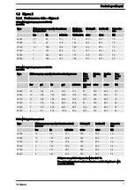
1.2.1  Performance data – Sigma 2

Type

Minimum pump capacity at maximum

back pressure

Maximum

stroke rate

Priming lift

Suction lift

Connector

size


bar

l/h

ml/stroke

Strokes/min mbar

mbar

DN

16050

10

49

11.1

73

190

500

15

16090

10

87

10.9

132

190

500

15

16130

10

128

10.8

198

190

500

15

07120

7

122

27.8

73

150

500

25

07220

7

223

28.1

132

150

500

25

04350

4

356

30.0

198

150

500

25

Type

Minimum pump capacity at maximum back pressure

Max‐

imum

stroke

rate

Priming

lift

Suction

lift

Con‐

nector

size


bar

psi

l/h

gph

ml/stroke Strokes/

min

mbar

mbar

DN

16050

10

145

58

15.3

11.1

87

190

500

15

16090

10

145

102

29.9

10.9

156

190

500

15

16130

10

145

150

39.5

10.8

232

190

500

15

07120

7

100

145

38.2

27.8

87

150

500

25

07220

7

100

263

69.4

28.1

156

150

500

25

04350

4

58

418

110.3

30.0

232

150

500

25

Type

Minimum pump capacity at maximum back

pressure

Priming lift

Suction lift

Connector

size


bar

l/h

ml/stroke

mbar

mbar

DN

16050

10

60

11.1

190

500

15

16090

10

105

10.9

190

500

15

16130

10

129

10.8

190

500

15

07120

7

150

27.8

150

500

25

07220

7

270

28.1

150

500

25

04350

4

360

30.0

150

500

25

All figures are guideline figures for water at 20 °C.
The priming lift applies to a filled suction line and filled liquid end - with

correct installation.

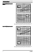
S2Ba with hygienic pump head at 50 Hz

operation

S2Ba with hygienic pump head at 60 Hz

operation

S2Cb with hygienic pump head

Product-specific part


7

Содержание 040830

Страница 1: ...ructions and the corresponding Operating instructions for the diaphragm motor driven dosing pump Sigma Both sets of operating instructions are only valid when read together EN Part no 986047 BA SI 098 08 21 EN Please carefully read these operating instructions before use Do not discard The operator shall be liable for any damage caused by installation or operating errors The latest version of the ...

Страница 2: ...nce data Sigma 3 12 1 3 2 Dimensional drawings Sigma 3 13 1 3 3 Spare parts lists for Sigma 3 14 1 3 4 Wetted materials 15 1 3 5 Performance diagrams Sigma 3 with hygienic pump head 15 2 General information 17 2 1 Safety chapter 17 2 2 Storage and transport 17 2 3 Installation hydraulic 18 2 4 Start up 18 2 5 Maintenance 18 2 6 Troubleshooting 19 2 7 Technical data 19 2 8 Standards and regulations...

Страница 3: ...mum stroke rate Priming lift Suction lift Con nector size bar psi l h gph ml stroke Strokes m in mbar mbar DN 10022 10 145 29 7 6 4 7 88 200 500 10 10044 10 145 55 21 4 4 5 172 200 500 10 07042 7 102 81 1 21 4 8 7 88 200 500 15 Type Minimum pump capacity at maximum back pressure Maximum stroke rate Priming lift Suction lift Connector size bar l h ml stroke Strokes min mbar mbar DN 10022 10 30 4 7 ...

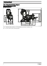
Страница 4: ...130 71 60 60 420 28 120 242 258 105 4 177 51 219 269 391 Fig 1 Dimensional drawing of Sigma 1 S1Cb with hygienic pump head dimensions in mm da1 150 mm space to remove the dosing head Dimensional drawing of Sigma 1 S1Cb with hygienic pump head Product specific part 4 ...

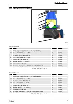
Страница 5: ...IN 11864 R 22x3 5 EPDM 6 1110595 5 Valve housing HD DN10 4435 2 1109441 6 Ball DIN 5401 D 5 8 G40 Al2O3 2 1110837 7 Valve seat HD DN10 4435 2 1109392 8 Multi layer diaphragm S1_a d70x37 PTFE EPDM 1935 1 1106069 Contents of the spare parts kit 1 1 4 Wetted materials Dosing head Valve seat valve housing connector section Seals Ball Diaphragm 1 4435 1 4435 EPDM Al2O3 PTFE O ring DIN 11864 R Sigma 1 w...

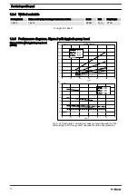
Страница 6: ...endent on the stroke length s B Dosing rate C dependent on the back pressure p p bar S C l h C l h A B 0 10 20 30 40 50 60 70 80 90 100 0 0 10 0 20 0 30 0 40 0 50 0 60 0 70 0 80 0 90 0 S1Cb Hygien 07065 10044 10022 0 1 0 2 0 3 0 4 0 5 0 6 0 7 0 8 0 9 0 10 0 0 0 10 0 20 0 30 0 40 0 50 0 60 0 70 0 80 0 90 0 07065 10044 10022 Fig 3 A Dosing rate C at maximum back pressure dependent on the stroke leng...

Страница 7: ...16090 10 145 102 29 9 10 9 156 190 500 15 16130 10 145 150 39 5 10 8 232 190 500 15 07120 7 100 145 38 2 27 8 87 150 500 25 07220 7 100 263 69 4 28 1 156 150 500 25 04350 4 58 418 110 3 30 0 232 150 500 25 Type Minimum pump capacity at maximum back pressure Priming lift Suction lift Connector size bar l h ml stroke mbar mbar DN 16050 10 60 11 1 190 500 15 16090 10 105 10 9 190 500 15 16130 10 129 ...

Страница 8: ...ic pump head DN15 dimensions in mm da1 150 mm space to remove the dosing head 170 60 60 82 5 120 267 282 446 426 28 231 0 5 339 339 5 130 205 99 da1 P_SI_0209_SW Fig 5 Dimensional drawing of Sigma 2 S2Cb with hygienic pump head DN25 dimensions in mm da1 150 mm space to remove the dosing head Dimensional drawings of Sigma 2 S2Cb with hygienic pump head Product specific part 8 ...

Страница 9: ... DN15 4435 2 1109062 8 Multi layer diaphragm S2_a d86 5x46 M8 PTFE EPDM 1935 1 1106066 Contents of the spare parts kit Tab 2 DN25 design Pos Article Quantity Order no 1 Single hinge clamp not included in the scope of delivery 2 O ring DIN 11864 R 28x3 5 EPDM 2 1110588 3 Connector section HD DN25 4435 2 1109596 4 O ring DIN 11864 R 40x5 EPDM 6 1110587 5 Valve housing HD DN25 4435 2 1109590 6 Ball D...

Страница 10: ...r S C l h C l h S2Ba Hygien A B 0 50 100 150 200 250 300 350 400 450 0 2 4 6 04350 07220 07120 16130 16090 16050 12 10 8 0 50 100 150 200 250 300 350 400 450 80 60 40 20 0 100 120 04350 07220 07120 16130 16090 16050 Fig 6 A Dosing rate C at maximum back pressure dependent on the stroke length s B Dosing rate C dependent on the back pressure p Sigma 2 S2Ba with hygienic pump head 50 Hz Product spec...

Страница 11: ... 16090 16050 12 10 8 0 50 100 150 200 250 300 350 400 450 80 60 40 20 0 100 120 04350 07220 07120 16130 16090 16050 Fig 7 A Dosing rate C at maximum back pressure dependent on the stroke length s B Dosing rate C dependent on the back pressure p Sigma 2 S2Cb with hygienic pump head Product specific part 11 ...

Страница 12: ...45 178 46 9 34 4 86 180 500 25 120190 10 145 257 67 8 34 6 124 180 500 25 120270 10 145 358 94 4 34 4 173 180 500 25 070410 7 102 447 117 9 86 7 86 190 400 32 070580 7 102 657 173 3 88 3 124 190 400 32 040830 4 58 961 253 5 92 6 173 190 400 32 Type Minimum pump capacity at maximum back pressure Priming lift Suction lift Connector size bar l h ml stroke mbar mbar DN 120145 10 186 29 3 180 500 25 12...

Страница 13: ... pump head DN25 dimensions in mm da1 150 mm space to remove the dosing head 177 5 113 107 70 50 28 120 267 275 249 451 455 51 457 406 211 136 da1 P_SI_0211_SW Fig 9 Dimensional drawing of Sigma 3 S3Cb with hygienic pump head DN32 dimensions in mm da1 150 mm space to remove the dosing head Dimensional drawing of Sigma 3 S3Cb with hygienic pump head Product specific part 13 ...

Страница 14: ...t HD DN25 4435 2 1109586 8 Multi layer diaphragm S3_a d123 5x75 M10 PTFE EPDM1935 1 1106065 Contents of the spare parts kit Tab 4 DN32 design Pos Article Quantity Order no 1 Single hinge clamp not included in the scope of delivery 2 O ring DIN 11864 R 34x5 EPDM 2 1110586 3 Connector section HD DN32 4435 2 1109621 4 O ring DIN 11864 R 52x5 EPDM 6 1109958 5 Valve housing HD DN32 4435 2 1109620 6 Bal...

Страница 15: ...ic pump head p bar S C l h C l h S3Cb Hygien A B 0 20 40 60 10 30 50 80 70 90 100 300 0 500 400 100 200 120270 120190 120145 0 1 6 10 12 9 7 5 0 300 500 400 100 11 8 4 3 2 200 120270 120190 120145 Fig 10 A Dosing rate C at maximum back pressure dependent on the stroke length s B Dosing rate C dependent on the back pressure p Sigma 3 S3Ba with hygienic pump head 50 Hz 1 Product specific part 15 ...

Страница 16: ...ngth s B Dosing rate C dependent on the back pressure p p bar S C l h C l h S3Cb Hygien A B 0 20 40 60 10 30 50 80 70 90 100 300 0 500 400 100 200 120270 120190 120145 0 1 6 10 12 9 7 5 0 300 500 400 100 11 8 4 3 2 200 120270 120190 120145 Fig 12 A Dosing rate C at maximum back pressure dependent on the stroke length s B Dosing rate C dependent on the back pressure p Sigma 3 S3Ba with hygienic pum...

Страница 17: ... CAUTION Extreme temperatures Liquid media ambient temperatures and heating or cooling equipment can cause extreme temperatures at the liquid end If necessary take appropriate measures to combat this Make sure that the wetted surfaces are not scratched or damaged The metallic wetted surfaces are electropolished with Ra max 0 8 μm Do not scratch or damage the wetted side of the diaphragm The sound ...

Страница 18: ...t atmospheric pressure Regularly Check the surfaces and seals for scratches and deposits refer to Ä Chapter 3 3 Cleaning manual on page 23 Regularly Check the seals of the hygiene valve and replace them if in doubt refer to the appropriate chapter Spare parts lists and Ä Chapter 3 3 Cleaning manual on page 23 The O rings can age faster than usual when exposed to high thermal loading in extreme cas...

Страница 19: ...emical when operating in an atmosphere at risk from explosion 115 C Of course the dosing head assumes the temperature of the liquid medium after a short time Consider putting in place appropriate protective meas ures Sound pressure level of the dosing heads when the pump is running 80 dB A ISO 11688 1 11 2009 2 8 Standards and regulations EN 1672 2 07 2009 Food processing machinery General design ...

Страница 20: ...cles when exposed to high thermal load is possible then shorten the maintenance intervals Make sure that the wetted surfaces are not scratched or damaged The metallic wetted surfaces are electropolished with Ra max 0 8 μm Do not scratch or damage the wetted side of the diaphragm Do not exceed the chloride content of the batching water see Ä Selected cleaning agents and parameters on page 22 and Ä ...

Страница 21: ...iate protective measures ProMinent metering pumps with hygiene pump head are fitted with tightly closing ball check valves which is why flushing liquid collects above the valves after the CIP cleaning in place stage It may be necessary to implement appropriate processes to remove this flushing liquid The pump needs to be stopped if you wish to fully purge the residual liquid 1 Pre flushing Remove ...

Страница 22: ...ing agent disinfec tant pH value 11 120 1 5 45 60 Disinfectant Max chloride con tent in the batching water mg l Concentration Dwell time min Max tempera ture C Acidic disinfectant based on peracetic acid 150 0 2 1 0 20 25 application variation 150 0 5 45 40 Acidic disinfectant based on haloacid phosphoric acid 150 0 5 1 0 20 25 Acidic disinfectant based on haloacid nitric acid 150 0 5 1 0 20 25 Ne...

Страница 23: ... the large single hinge clamps and take care of the parts NOTICE Only tighten the single hinge clamps by hand Do not use any tools or extension B1285_3 5 4 3 2 1 6 7 Fig 14 Cross section through the Sigma Hygiene liquid end 1 O ring 2 Connector section 3 Valve housing 4 Ball 5 Valve seat 6 Dosing head 7 Diaphragm n Risk of confusion Once assembled the balls 4 and their valve seats 5 must be seated...

Страница 24: ...e valve seat was pointing to the ball and re assemble the valve in the same way n The direction arrows of both connection pieces 2 must point upwards once assembled Notes on cleaning metering pumps with hygienic pump head 24 ...

Страница 25: ...eres CAUTION Damage due to the possible falling of the heavy Sigma 3 dosing head types 070410 070580 040830 and 041030 Weight 32 kg Use lifting straps to move the large dosing head B1285_3 5 4 3 2 1 6 7 Fig 15 Cross section through the Sigma Hygiene liquid end 1 O ring 2 Connector section 3 Valve housing 4 Ball Notes on cleaning metering pumps with hygienic pump head 25 ...

Страница 26: ...ted to the conditions subsequently required 11 Place the dosing head with the screws onto the diaphragm the suction connector should be pointing downwards when the pump is subsequently installed 12 Initially slightly tighten the screws then tighten crosswise to 25 of the tightening torque note the laser engraving see Ä Tightening torques on page 26 13 Screw the diaphragm rupture sensor into the do...

Страница 27: ...4 Piston 5 Diaphragm rupture sensor 6 Cylinder red 7 Cover transparent 2 If the piston of the diaphragm rupture sensor see item 4 should become dirty or damp clean both it and the hole in which it runs 3 Check whether it can move freely in the hole 4 Reassemble the clean diaphragm rupture sensor with the clean piston 5 Test the diaphragm rupture sensor Optical diaphragm rupture sensor 1 Unscrew th...

Страница 28: ...e transparent cover onto the dia phragm rupture sensor and then continue at the top by assembling the diaphragm Electrical diaphragm rupture sensor 1 Press the piston of the diaphragm rupture sensor into the dosing head approximately 4 mm using the blunt smooth object until the monitor triggers an alarm CAUTION Feed chemical may escape Feed chemical can escape in the event of a dia phragm rupture ...

Страница 29: ...29 ...

Страница 30: ...30 ...

Страница 31: ...31 ...

Страница 32: ...986047 8 en_GB 2021 ProMinent GmbH Im Schuhmachergewann 5 11 69123 Heidelberg Germany Telephone 49 6221 842 0 Fax 49 6221 842 419 Email info prominent com Internet www prominent com ...

Отзывы: