DE
EN
FR
IT
ES
NL
RU
PL
SE
FI
Select the desired speed by pressing the membrane keyboard. To increase the speed, press the button
(L)
and
to reduce the speed, press the button
(N)
. The value set is then shown as a two-digit value on the display
(J)
.
Speeds of up to 10,000 rpm are displayed with a decimal place
, whereas speeds of 10,000 rpm and
higher are shown without a decimal place .
The speed regulation can be set as follows and is shown accordingly on the display:
From the initial speed of 4,000 rpm to the 10,000 rpm in steps of 500.
From the speed range between 10,000 rpm and 30,000 rpm in steps of 1,000.
When the buttons are pressed down continuously, the display scrolls rapidly through the different speed levels.
Please note:
Differences in the running noises between clockwise and anti-clockwise direction are normal and caused by
the grinding-in of the carbon brushes or by the running-in of the ball bearings.
Please note:
Before using the device for the first time, it is absolutely necessary to run the handpiece for approx.
30 minutes at approx. 8,000 rpm. This is necessary to ensure that the carbon brushes are ground in.
G. Standby function
1. On the device:
The button
(O)
offers a “Pause - standby function”. The values set are maintained for the duration of the pause.
During this process, the speed and direction of rotation selected last are shown with an additional pause
symbol. When this button is pressed again, the device continues to run with the previous settings.
2. On the handpiece:
The same function can be triggered by actuating the microswitch
(C)
on the handpiece.
H. Overload protection for the handpiece motor
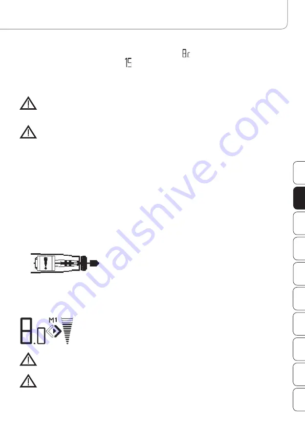
• In the event of any blockage or an overload of the handpiece, the speed and suction turbine are
switchedoff after approx. 5 seconds. On the display
(J),
the following error message is shown:
• After approx. 8 seconds, this reading disappears and the device is in the standby mode.
I. Controlling the suction capacity
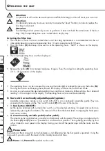
• The suction capacity can be adjusted in 13 steps. By pressing the button
(S),
the suction capacity is
increased; by pressing the button
(Q),
it is reduced.
• On the display, the capacity value set is shown in a bar chart on the right side. The suction capacity
chosen has a dark background.
Please
note:
For most cases, the medium suction capacity setting is sufficient.
Please
note:
The suction air flow serves at the same time as cooling for the micromotor. When the device is in operation,
the suction runs permanently, at least at the lowest setting. The suction function cannot be switched off!
O
PERATING
THE
UNIT


