background image

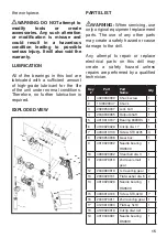
16

20

3150150021

Brush holder 
support

2

21

2030070041

Brush holder 

2

22

1230010096

Carbon brush

2

23

2020150060

Middle cover

1

24

4010010050

Bearing 609Z

1

25

3140090015

Buffer

1

26

1020010005

Stator

1

27

3011020004

Housing

1

28

1010010006

Rotor

1

29

1061050001

Switch

1

30

4010010034

Bearing 607Z

1

31

3140040003

Bearing sleeve

1

32

4030010099

Screw ST3.9x14

3

33

2030050002

Cord clamp

1

34

1140020048

Chuck key

1

35

3140010050

Cord guard

1

36

1190030008

Cord set

1

37

4050010009

Hex bolt

1

38

3120070042

Mounting collar

1

39

3120070010

Auxiliary handle

1

WARRANTY

1.  PROMAKER

®

, through its PX2 

warranty for power tools, has the 

following characteristics:

•  It covers the products for 2 years 

from the date of purchase against 

any defect in its operation, for 

faults in the materials or labor 

used in its manufacture.

•  Provides  2  years of free 

maintenance service and labor 

for replacement of consumables.

•  Provides a trial period of 

2  months  where you can 

exchange the tool for a higher 

capacity one if the original does 

not meet your requirement, by 

paying the difference in price.

•  All the attributes offered by the 

warranty are valid presenting 

the original purchase invoice.

2. For warranty service, please 

contact the present the warranty 

card and the original invoice for the 

warranty service.

3. This Warranty DOES NOT 

applies for:

•  Transportation damages after sales.

•  Services not provided by our 

authorized service centers.

•  Accessories and spare parts, if 

any, provided in the package.

•  Damage resulted by improper 

commercial or industrial use, since 

this machine has been designed 

to withstand hard working days 

with breaks so as not to expose it 

to overheating.

EC DECLARATION OF 

CONFORMITY

We hereby declare that the machine 

described below complies with the 

relevant basic safety Directives, both 

in its basic design and construction 

as well as in the version put into 

circulation by us. This declaration 

shall cease to be valid if the 

machine  is  modified  without  our 

prior approval.

Product: 1/2”(13mm) Hammer Drill

Содержание PRO-TP800

Страница 1: ...1 2 13mm Hammer Drill User s Manual Model No PRO TP800 English 2 I Espa ol 22...

Страница 2: ...ARNING Use hearing protection particularly during extended periods of operation of the tool or if the operation is noisy SAVE THESE INSTRUCTIONS FOR REFERENCE WEAR A DUST MASK THAT IS DESIGNED TO BE U...

Страница 3: ...let Never modify the plug in any way Do not use any adapter plugs with earthed grounded power tools Unmodified plugs and matching outlets will reduce risk of electric shock Avoid body contact with ear...

Страница 4: ...balance at all times This enables better control of the power tool in unexpected situations Dress properly Do not wear loose clothing or jewelry Keep your hair clothing and gloves away from moving pa...

Страница 5: ...ts own cord Contact with a live wire will make exposed metal parts of the tool live and shock the operator Use auxiliary handles supplied with the tool Loss of control can cause personal injury Servic...

Страница 6: ...r become unbalanced during use Make sure the spindle has come to a complete stop before touching the chuck or attempting to change the drill bit Always make sure the chuck is tight and the drill bit f...

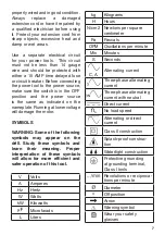
Страница 7: ...e motor SYMBOLS WARNING Some of the following symbols may appear on the drill Study these symbols and learn their meaning Proper interpretation of these symbols will allow for more efficient and safer...

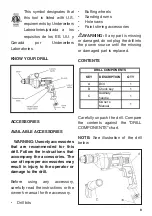
Страница 8: ...in injury to the operator or damage to the drill Before using any accessory carefully read the instructions or the owner s manual for the accessory Drill bits Buffing wheels Sanding drums Hole saws Pa...

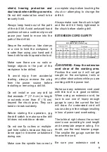
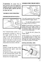
Страница 9: ...ck is turning b There is no dead center position for the forward reverse switch The tool will run only when it is in either the full left or full right position VARIABLE SPEEDTRIGGERSWITCH Fig 2 This...

Страница 10: ...ll is started 5 Finish tightening the chuck jaws by inserting the chuck key 4 into one of three holes 5 in the chuck body Rotate chuck key clockwise until drill bit is held firmly in place by the chuc...

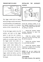
Страница 11: ...ll will continue to run at full speed To release the trigger switch lock button pull the trigger switch back and then release the trigger INSTALLING THE AUXILIARY HANDLE Fig 6 Install the auxiliary ha...

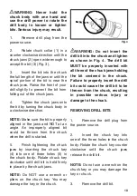
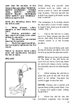
Страница 12: ...t from slipping off center as the hole is started The workpiece to be drilled should be secured in a vice or with clamps to keep it from turning as the drill bit rotates Fig 7 1 Check the drill bit to...

Страница 13: ...fe of the drill bit and improve the cutting action If the bit jams in the workpiece or if the drill stalls release the trigger switch immediately Remove the bit from the workpiece and determine the re...

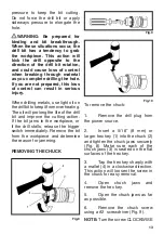
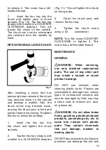
Страница 14: ...ply with a mallet in a CLOCKWISE direction Fig 11 This will tighten the chuck on the spindle 3 Open the chuck jaws and remove the hex key 4 Tighten the chuck screw using a 2 screwdriver NOTE Turn the...

Страница 15: ...use damage to the drill Any attempt to repair or replace electrical parts on this drill may create a safety hazard unless repairs are performed by a qualified technician Key Part Part Name Qty 1 40200...

Страница 16: ...vides a trial period of 2 months where you can exchange the tool for a higher capacity one if the original does not meet your requirement by paying the difference in price All the attributes offered b...

Страница 17: ...NOTES...

Страница 18: ...NOTES...

Страница 19: ...NOTES...

Страница 20: ...www promakertools com...

Страница 21: ...Taladro Percutor de 1 2 13mm Manual del Usuario Modelo No PRO TP800...

Страница 22: ...as inadecuadas pueden causar lesiones graves si se rompen durante el funcionamiento de una herramienta el ctrica Advertencia Use protecci n auditiva particularmente durante per odos extendidos de oper...

Страница 23: ...de trabajo limpia y bien iluminada Las reas de trabajo desordenadas u oscuras invitan a accidentes No utilice herramientas el ctricas en atm sferas explosivas como tampoco en presencia de l quidos in...

Страница 24: ...nci n al operar herramientas el ctricas puede resultar en lesiones personales graves Use equipo de protecci n personal Siempre utilice protecci n ocular Equipos de Protecci n tales como mascarilla ant...

Страница 25: ...seguridad reducen el riesgo de arrancar la herramienta accidentalmente Guarde las herramientas inactivas fuera del alcance de los ni os y no permita que personas que no est n familiarizadas con la Her...

Страница 26: ...uir esta norma reducir el riesgo de descarga el ctrica incendio o lesiones graves Siempre use protecci n ocular Cualquier herramienta el ctrica puede lanzar part culas extra as a los ojos y causar da...

Страница 27: ...e solo 120V ADVERTENCIA Mantenga libre el cable de extensi n dentro del rea de trabajo Coloque el cable de tal manera que no quede atrapado dentro de la pieza de trabajo las herramientas u otros obst...

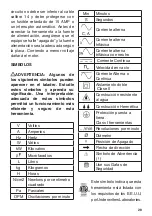
Страница 28: ...y seguro de esta herramienta V Voltios A Amperios Hz Hertz W Vatios kW Kilovatios Microfaradios L Litros kg Kilogramos H Horas N cm2 Newtons por centimetro cuadrado Pa Pascales OPM Oscilaciones por m...

Страница 29: ...s instrucciones del manual del usuario para el accesorio Brocas del taladro Discos pulidores Tambores de pulido Sierra de agujero Accesorios de agitaci n de pintura ADVERTENCIA Si falta alguna pieza o...

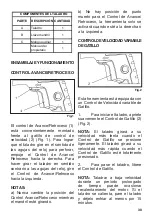
Страница 30: ...eso mientras el mandril est girando b No hay posici n de punto muerto para el Control de Avance Retroceso la herramienta solo se activar cuando est a la derecha o a la izquierda CONTROLDEVELOCIDADVARI...

Страница 31: ...4 Apriete las mordazas del mandril sobre la broca girando el cuerpo de el mandril en el sentido de las agujas del reloj NOTA Aseg rese de que la broca est completamente alineada en las mordazas y NO e...

Страница 32: ...el interruptor de gatillo en posici n ACTIVADA tire hacia atr s del Control de gatillo para iniciar la perforaci n Contin e presionando el gatillo hasta que se alcance la m xima velocidad Empuje el b...

Страница 33: ...tector auditivo y mascara antipolvo al perforar concreto 3 Mandril en forma adecuada 4 Broca en buenas condiciones y apretado correctamente Incumplir estas normas de seguridad aumentar el riesgo de le...

Страница 34: ...ro ADVERTENCIA Debe estar preparado para casos en que la broca se tranca o se fractura cuando se producen estas situaciones la broca tiende a afectar la pieza de trabajo Esta acci n har retroceder el...

Страница 35: ...ete las pesta as del mandril firmemente Fig 10 Golpee la llave hexagonal fuertemente con un mazo en sentido anti horario Esto aflojar el mandril del eje El mandril puede ahora ser desenroscado y retir...

Страница 36: ...nen productos qu micos que pueden da ar debilitar o destruir el pl stico NO abuse de las herramientas el ctricas Las pr cticas abusivas pueden da ar la herramienta y las piezas de trabajo ADVERTENCIA...

Страница 37: ...ela plana dia 6 2 14 4010020029 Cojinete de agujas HK0609 1 15 4030010106 Tornillo ST3 9x19 7 16 2040070011 Engranaje grande 2 Nivel 1 17 4120010004 Llave plana 5x10 1 18 4100020010 Clip circular dia...

Страница 38: ...o con el Centro de Servicio Autorizado Presente la tarjeta de garant a y la factura original para el servicio de garant a 3 La presente Garant a NO aplica en Da os por transporte despu s de las ventas...

Страница 39: ...NOTAS...

Страница 40: ...www promakertools com...

Отзывы: