14
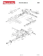
ASSEMBLY CHART -SANDING BELT DEVICE
10
Step
1.
Loosen the screw (1), remove (2) Rotor Shaft Cap, and tighten the screw (1).
2.
Remove the (3) screw, put on the (4) Safety Cover, and tighten the (3) screw.
3.
Assemble (5) Adapt
or
, (6) Disc Washer, (7) Buffer, (8) Hex Nut, (9) Adapt
or
Cap in sequence and fix it to
the
shaft.
9
Curve Sanding
1.
Put frame assembly to horizontal position.
2.
Loosen screw A and B showed in figure.
3.
open roller covers to proper position and fix it.
4.
This machine is now ready for the
operation of curve sanding.
8
1.
This machine is designed to allow the sanding
belt to be operated vertically or horizontally
at your comfortable choice.
2.
Use 6mm hex. wrench may loosen and
tighten cap screw to adjust frame assembly in
proper angles.
3
1
2
4
5
6
7
8
9
Содержание 323BF-BP
Страница 9: ...9 UNPACKING AND CHECKING LIST LOOSE PARTS IN RECTANGLE BOX GRINGER ASSEMBLY Q TY 1...
Страница 10: ...10 LOOSE PARTS IN RECTANGLE BOX...
Страница 16: ...8 323BF BP Exploded View...


