


4
3.2. CONNECTION
The unit has to be installed following the
prevailing regulations for electrical installations.
In the “mounting box” model, the grommets
provided with the unit are to be installed, removing the
relevant dies (this should be done with the connection
cover in place and screwed to avoid possible
breakage).
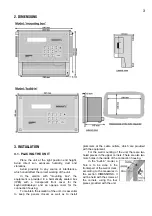
In the “build-in” model the terminals are placed at
the back and they are the
connector type. On placing
the terminals check that they
have been introduced in the
guides, as it is shown in the
figure.
It is advisable to connect the cables to the
terminals with terminal connections, which are also
included with the unit.
There is also a protection box for all the
terminals, in case there is a risk of electrical sparks
from storms entering the cables.
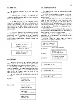
3.2.1. SUPPLY TO THE EQUIPMENT
Before connecting the unit, it is necessary to
check its identification label where the characteristics
of the power feeding are to be found.
•
Power feeding at 220 Vac:
A 6 amp magneto-thermal switch is to be included
in the installation. It will be used as a disconnection
device and it has to be placed near the unit and at an
accessible place for the user.
It is recommendable to do this as directly as
possible, avoiding that the same cable supplies other
sections. Use cable of the H05VV-F type, 1mm
2
.
A fuse (general fuse) and a varistor protect the
mains input. The varistor might short-circuit the fuse
automatically, on detecting an overload on the line
(lightning, etc.); replace it with one of the same
characteristics.
For unstable or fluctuating voltages use grid
stabilisers.
If the unit is to be disconnected from the power line
during several weeks, it is advisable to remove the
bridge marked as “J4” (next to the battery) in the circuit
placed behind the keyboard, and insert it again before
connecting it to the power line.
•
Power feeding at 12 Vdc:
Check the polarity of the terminals.
Connect two direct cables from the battery to the
equipment feeding (+12-) avoiding that those cables
supply other units or elements.
If the battery is far away from the controller, use
high section cables and make a reduction when
entering the equipment.
The input is also protected with a fuse and a
varistor.
To replace the fuse, half turn the fuse cover and
insert another of the same value.
3.2.2. CONNECTING THE EARTH TERMINAL
The “build-in” model has a terminal screw to
connect the protection earth terminal, and which is
placed near the feeding terminals.
In the “mounting box” model, a protection
terminal is not needed, but it has got a box terminal
marked as:
CP
to be connected to the earth
terminal.
Both the earth and box terminals are used to
protect the unit by directing all electrical sparks
produced by the internal gas discharger to the earth.
These sparks can come in through the outlet cables.
3.2.3. CONNECTING INPUTS
The contacts that join the inputs with the
common have to be normally open and free of
tension. Avoid placing the cables of these inputs near
power lines, dividing them into two separate groups.
- TERMINAL NUMBER 3. Detector of flow
circulation. In the version by time, connect a testing
spike or external programmer or join it directly to
terminal number 6 if circulation is continuous. In the
version by volume connect a volumetric transmitter of
impulses.
- TERMINAL NUMBER 4. If the unit has a
differential pressure gauge which detects when filters
are dirty, connect it to this cleaning start input and to
the common (CE).
- TERMINAL NUMBER 5. Breakdown input to
which one or several securities (maximum/minimum
pressure gauges, etc…) will be connected, if
necessary. These will only be accepted when a filter
cleaning is taking place, leaving the unit out of work.
- TERMINAL NUMBER 6 (CE). Input common.
3.2.4 CONNECTING OUTLETS
Connect the solenoids, relays, etc. between the
common of outlets and the corresponding outlet.
Do not surpass the charge per outlet and
common.
The “outlet fuse” protects from overloads and
short-circuits. To change it, just half turn the cover of
the fuse holder, take it out and replace it with a similar
one.
The outlets are isolated from the interior circuitry
by relays and protected by a varistor in each one.
Содержание Agronic
Страница 10: ...10 R 910 1...


