User Guide
DVS-21
02/2018
• V.1.0 • L. Wolle
108/131
© 2017 ProCom
®
Professional Communication & Service GmbH • Technical changes reserved.
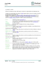
11.2 CPU
Страница 1: ...s 10 Sprache Language 10 Default 10 Color 10 Templates 10 3 2 RS232 settings 11 4 Online functions 11 4 1 Monitor 12 Filter function 13 4 2 Data transfer 13 Userbank List 14 Connection via modem 14 4...
Страница 2: ...1 Configure module 31 Address description 32 Power consumption 32 6 4 Program overview 32 Add program 32 Edit program 33 Copy program 33 Filter programs 33 Example 33 7 Modules 34 7 1 SV01 34 7 2 CPU...
Страница 3: ...oh 54 7 14 V100 55 Impedance measurement 55 Acknowledgment 56 Recommended Programs 57 7 15 USE2 58 Operation mode PBX 58 Operation mode Telephone subscriber 58 Operation mode Doorline 59 Operation mod...
Страница 4: ...Call 85 9 10 LB connection 86 9 11 LB forwarder 87 9 12 PA Public address 87 9 13 Public address 2 PA remote local 88 9 14 AF Switching 90 9 15 USE1 Intercom 90 9 16 Remote Intercom 91 9 17 Remote Int...
Страница 5: ...105 10 12 Special trigger lines 105 10 13 Byte Edit Universal32 106 11 Anhang 107 11 1 SV01 107 11 2 CPU 108 11 3 LCPU 109 11 4 4FTR 110 11 5 4NSA 112 11 6 4DAV 113 11 7 4NPA 114 11 8 4ZZA 115 11 9 4I...
Страница 6: ...ll defined control information that an exchange can send or receive is called lines A Line has either status 0 or 1 Per Port 120 omnidirectional lines are supported Lines can be realised either as a s...
Страница 7: ...allation is the main installation The links in the start menu on the desktop and the shortcut list as well as the ICS file type are linked to this installation Note Duplication by simply copying an in...
Страница 8: ...valuation of recordings of telegrams Compare files Byte by byte comparison of two program files WAV Player Playback of a WAV File from the wav directory Tone generator external program for the generat...
Страница 9: ...Simulation By simulating messages can be sent to modules telegrams from modules can be emulated and flags can be switched Right side of the toolbar see System configuration New system Create a new sy...
Страница 10: ...he Address description list V100 Loudness Initial values for the newly created amplifier Monitor Live The display is cleared once the number of entries has been reached Monitor Redirect file In the ca...
Страница 11: ...Connection Group and the AT parameters of the modem in use can also be corrected manually Initialization and selection can be tested by means of the Modem init check button 4 Online functions All fun...
Страница 12: ...lay position Clear display clears the content of the display Marking off resets all marking of entries that have been marked by selecting this checkbox in the left hand column In the case of the check...
Страница 13: ...the filter function to a specific Address Line or Flag By using the Hide acknowledgments and w o call station test display selection fields no acknowledgment to a telegram regarding module testing or...
Страница 14: ...on whether a program has already been opened for configuration in the System data component If no program is open then on completion of transfer the program that has been read is transferred to the S...
Страница 15: ...ommunication Service GmbH Technical changes reserved 4 3 Firmware DVS update This module is used to update the firmware of the system CPU The system has two code banks This offers the option of transf...
Страница 16: ...used to update the system time used by the system CPU PC Time apply Sets the system time of the CPU to the PC Notebook time Manual apply Sets the system time of the CPU to the manually entered time R...
Страница 17: ...ram number in Byte 1 The Editor displays a copy of the database and provides direct access to the content This means that any program can be changed without an input mask being required Background kno...
Страница 18: ...hich the filter string applies are displayed Filter negative Entries to which the filter string applies are not displayed Exclusion filter Measure time Any entry can be set as a starting point for a t...
Страница 19: ...Guide DVS 21 02 2018 V 1 0 L Wolle 19 131 2017 ProCom Professional Communication Service GmbH Technical changes reserved 5 4 Speech storage Recording playback and testing of the DSS1 Speech storage mo...
Страница 20: ...s Port Address and port of the module DSS1 Functions PLAY RAM Playback from RAM PLAY FLASH Playback from FLASH RECORD RAM 4NSA WAV SYNC To record a WAV file with automatic starting of playback Connect...
Страница 21: ...R2 etc Allocation overview provides the Station number associated with the address and port Address allocations lists the descriptive texts of the module addresses Plausibility report lists all possib...
Страница 22: ...ges provide information A list of possible errors and notes Destination call station is not programmed This message appears if a connection has been programmed from the call station indicated in the l...
Страница 23: ...changes reserved 5 7 Dependencies This forms shows the internal table of the previously archived version dependencies When writing a configuration file in a system all versions of the programs used a...
Страница 24: ...omponent This consists of 4 sub pages for higher level data and settings 6 1 System data General data Client agent details The input fields are partially preconfigured automatically and should be chec...
Страница 25: ...ess a station then an FSK fault report is triggered on the associated port of the 4NSA module and a related general fault report on the SV01 Speech time limit 0 none Active intercom calls are disconne...
Страница 26: ...configured by means of the expanded dialog DCF 77 Synchronization Synchronization takes place either hourly or at a fixed time always on the hour DCF 77 not found If the receiver is not connected or...
Страница 27: ...ent buttons all available stations and amplifiers are set to the specified standard level Definition of the level values Normal Level is the level that is used during a call Call Level is the level th...
Страница 28: ...s how rapidly the system can may accept consecutive incoming calls The acceptance of incoming calls can be blocked by means of the NAND call flag field The Flag OUT is triggered if a connection is est...
Страница 29: ...ied The next vacant number is suggested automatically as the station number The number of keys field located below it contains the possible V that is available for the selected type of station Confirm...
Страница 30: ...ly and the CPU1 processor If a redundant standby CPU is provided then positions 1 4 are occupied 2xSV01 2xCPU1 Select module rack The type of Module rack that is in use can be selected on the right ne...
Страница 31: ...uration This is indeed only possible in the case of non programmed modules Already programmed modules cannot be moved directly It is recommended that a new module be placed and that the programming be...
Страница 32: ...ion is based on the boot and operating behavior of the respective module If the sum of all currents reaches the load limit of the specified supply module a colored symbol is superimposed in the graphi...
Страница 33: ...button or by means of the right hand mouse menu This is then helpful if multiple very similarly configured programs are required which can the be adapted by changing the values Filter programs Some to...
Страница 34: ...For switching tasks two floating optocoupler inputs AC DC and a configurable relay output are available Relay Configuration Fault indication Relay is fault indication relay no fault closed contacts A...
Страница 35: ...it Init for fault report lines in loop Default 200 Main loop passes unit Time in which the V25 attempts to initialize the supplementary error message Line before the error message program switches fro...
Страница 36: ...ys flashing with test telegram LEDs are off after init phase short flashing in case of test frames always on LED s are on after init phase always off LED s are off after init phase E1 Clock synchroniz...
Страница 37: ...nection Voice over IP ISDN with enhanced functionality Additional slot for a 2Mbit or ISDN function module Configuration and terminal assignment of the modules 2Mbit ISDN can be found at 4FTR The slot...
Страница 38: ...f module the operating mode of the ports has to be selected according to the module assembly Firmware BUS CPU If it is a module with bus CPU the option has to be activated Modules of newer design with...
Страница 39: ...Corresponding additional priority lines are assigned automatically The priority of a caller denoted under Allowed call numbers determines which of the three control lines is initiated during a call Di...
Страница 40: ...ion line master Modem Slave Operating as a transmission line the opposite side master no Modem with pure AF frequency the modem can be disabled AF controlling Activation of self monitoring and adjustm...
Страница 41: ...ides for the power supply for station with internal 4W amp voice transmission and control information The power supply is fused and sustained short circuit proof If the 25W amplifier within the statio...
Страница 42: ...dule Level outgoing AF output attenuation from module to external device Display and control elements LEDs GREEN ON Outgoing connection is active GREEN FLASHING fast Incoming connection is active GREE...
Страница 43: ...ishes between call and busy Level incoming AF input gain from the external device to the module Level outgoing AF output attenuation from module to external device Line function Port 1 4 Line 1 Call l...
Страница 44: ...s per segment are available Record permanently stored Recording is done with the tool Speech storage Menu Tools Speech storage Playback is done manually by using control lines Temporary record during...
Страница 45: ...und free busy Delay Free and busy tone generate Delay of the output x 50ms due to reception transmission switching in radio magazine Line function Port 1 4 Line 1 M CPU DSS1 Busy Line 2 CPU M 420Hz 1...
Страница 46: ...or 0 8A at 125V AC Switching of large loads or consumers at mains voltage 230V may only take place if an additional external fuse is used Depending of the firmware of the module the following operatin...
Страница 47: ...the optocoupler is switched on the lines are synchronized for verification Transmission and reception are displayed by a flashing green signal at LED AI Synchrony double flash Differential mode by sin...
Страница 48: ...high Delay time till triggering of alarm factor 2 secs Timer Alarm low Delay time till triggering of alarm factor 8 millisecs Total time High Low Line function Port 1 4 Line 3 CPU M Relay Line 5 M CP...
Страница 49: ...e public address The module detects a public address by the relay closing with Line 3 and generates the voice acknowledgment if the level is sufficient To switch the relay e g for impedance measuremen...
Страница 50: ...d jumper must be closed on each of the 4 ports on the backplane slot FAC Logic activates the FAC operation mode for all 4 ports Line function Port 1 Line 18 M CPU Alarm triggered Line 19 M CPU System...
Страница 51: ...any control tasks In and outputs are referenced to 0V of the system supply voltage typ 48v without glavanic isolation The absolute voltage range of the inputs is 24V to 60V The output current is limit...
Страница 52: ...he measured values are recorded and calculated continuously In normal operation the output is only activated by enabling line 1 right at the beginning of a PA Line function Port 1 4 Line 1 CPU M Measu...
Страница 53: ...m USE1 intercom only up to DVS Firmware 7 21 Connection starts with audio channel Preferential channel by which the establishment of a connection is initiated Own exchange No Unique system number in s...
Страница 54: ...rol line permanently Controlling timer Timeout for maximum PA duration in seconds Test announcement No Sending line 100 to Set of the USE1 module activates the test mode By sending a line to port 3 or...
Страница 55: ...eld Interval time 0 always controls the amp Interval time x The amp is switched off when the call is accepted It is reactivated once the Interval time has been exceeded Standby amplifier Configures th...
Страница 56: ...e Line function Impedance measurement Control by program Impedance measurement Port 1 Line 3 CPU M Indication that impedance is too high red LED Line 4 CPU M Indication that impedance is too low red L...
Страница 57: ...RED ON Error no power supply overload impedance error GREEN ON Level display RED ON Overload display Backplane connectors SPK1 1 Amplifier SPK2 2 Amplifier SPK3 3 Amplifier SPK4 4 Amplifier Connectio...
Страница 58: ...tgoing AF output output attenuation from module to external device Number of suffix digits Number of DTMF suffix digits Speech timer Time after which the connection is disconnected compulsorily Backpl...
Страница 59: ...irmware PIC1 2104d_lon4_ob5 PIC2 2211 beta DVS Firmware ab 7 23 ICS Version 7 00 Rev 011 Transparent connection of analog telephone connections of Type USE2 e g remote modem via 2Mbit line connected b...
Страница 60: ...l of the hybrid circuit Polarization Positive or negative overlapping Level incoming AF input amplification from external device to module Level outgoing AF output attenuation from module to external...
Страница 61: ...ange 60 95 1 9 4 6W at 1 kOhm Default 80 3 2W at 1 kOhm Timer count switch off time after voice detection Value 255 prevents a switch off Dedicated line Range AF Response threshold of voice detection...
Страница 62: ...specific Connection of visual display workstations made by Vossloh via an analog telephone interface A connection is set up with the desired PA target by means of a specific DTMF suffix 6 tones A DTMF...
Страница 63: ...no longer required as from 4LSL Firmware 4102 Line function Port 1 Line 5 CPU M Begin measuring Switch on tone generator Line 6 CPU M Measurement completed Tone generator off Line 7 CPU M Begin measu...
Страница 64: ...y is disabled if the impedance measurement detects a short circuit AD Converter U Voltage threshold at AD Converter of the voltage path AD Converter I Voltage threshold at AD Converter of the current...
Страница 65: ...n at the time set in Day and Night Note Operation with temperature compensation requires the Flag timing program to send the Module a timestamp every hour Online control This dialog is used for active...
Страница 66: ...surement takes place with the loudspeaker circuit disabled Line 11 CPU M Automatic measuring process Line 12 CPU M Automatic calibration process Line 13 CPU M Earth fault report from TG01 Port Identif...
Страница 67: ...th fault Input Line 13 Line 16 M CPU Any port with impedance error short circuit or line break Display and control elements Normal mode LEDs M GREEN OFF no measurement GREEN ON measurement active GREE...
Страница 68: ...odule is designed to connect UZ ELA modules UZ ELA Control sub center for loudspeaker system German derivation UnterZentrale f r Elektronische LautsprecherAnlage All interfaces RS485 are galvanic isol...
Страница 69: ...anual attenuation of 4 loudspeaker lines This module acts within the programming as a placeholder for documentation purposes No configuration required Display and control elements Switches Rotary cont...
Страница 70: ...114 keys 4 wire technology as a built in call station PMK with 16 96 keys 4 wire technology as a weatherproof outdoor call station WPS xx with 4 8 toggles 2 and 4 wire technology extension units with...
Страница 71: ...can be operated with a 25 W Booster amplifier The weatherproof call stations WPSxx have a built in amplifier Into the Desktop and Flush mount call stations the external amplifier BA 25 has to be addi...
Страница 72: ...ys are connected to the 24LI module and the AF line is connected to a 4NPA module 24 lines keys can be connected to a 24LI module AF lines of four stations can be connected to a 4NPA module General da...
Страница 73: ...4M Name Labeling for the Measuring mic The button Get adopts a noted description from Address description 8 6 Separate amplifier Spatially separated analog amplifiers can be controlled by using the Se...
Страница 74: ...els available with 1 being the highest Priorities are dealt with on destination If a program finds an occupied destination the priorities of both programs are compared If the priority of the new conne...
Страница 75: ...ing playback Playback can be stopped see Example 1 Address Port Address and port of the station Line Line key for preselection or to start playback Preselection duration An announcement with chime mus...
Страница 76: ...d off by this flag or switching on can be prevented Flag OR IN The program can be switched on by this flag Flag OUT 1 2 OUT The flag is switched on if the program is activated Further programs can be...
Страница 77: ...nouncement with connectible chime Programming example DSS1_PA_Gong_2 Targets permanently assigned Chime selectable without Chime 1 Chime 2 Example 3 4 Announcement with variable target selection and c...
Страница 78: ...back of recorded tones or speech from the DSS1 module Operation mode Speech storage Priority Handling of priorities see Section 9 1 Input Address Port Line Address port and line of the module which re...
Страница 79: ...optional Priority Handling of priorities see Section 9 1 Codec Audio compression method by which the codec handles the actual connection The options are Law default ADPCM 7kHz and aLaw see Section 9 1...
Страница 80: ...t is programmed on a permanently occupied station e g control station It assumes control of calls and ends them A connection can be set up from both sides The program requires a higher priority than t...
Страница 81: ...configuration as a conference each to each Priority Handling of priorities see Section 9 1 Codec Audio compression method by which the codec handles the actual connection The options are Law default...
Страница 82: ...us must be conveyed explicitly Output Busy flag OUT The flag is switched on if the program switches to a Busy status Set group busy indication The program activates a Busy status if the specific stati...
Страница 83: ...tation The fixed AF channel specified under Audio channel Radio AF is used 26 27 28 29 see Table Fixed audio channels of the DSS1 module When pressing the PTT key the Line and the Flag OUT specified u...
Страница 84: ...smit switch by means of a relay of the module 4IOS Flag OUT Transmit switch alternatively programmed by means of Flag Timer Section timer Maximum time for which the program remains keyed in radio cove...
Страница 85: ...be activated for adaptation to specific requirements 9 9 AllCall The AllCall program functions locally Only destinations to which a voice connection can be established from the specific station by me...
Страница 86: ...9 10 LB connection Program for LB connections and LB repeater via Module USE2 LB Local Battery operation by means of a local battery without central supply crank and field phones Audio channel incomin...
Страница 87: ...odec Audio compression method with which the codec handles the actual connection The options are Law default ADPCM 7kHz and aLaw see Section 9 1 Own Analog Selects the type of call station ProCom or a...
Страница 88: ...ing long distance line Long distance line Long distance line Intermediate system connection of incoming outgoing long distance line Long distance line Amplifier Destination from incoming long distance...
Страница 89: ...The ports of the relay module are permanently linked to the amplifier fields Example 1 Amplifier 1st port of the relay module etc Acknowledgment processing AND PA acknowledgment of all lines must be d...
Страница 90: ...PA amplifier and to illuminate the keys Control lines over and above the available number of keys will result in no illumination taking place Channel Permanently assigned E1 channel for AF transmissio...
Страница 91: ...station ProCom or Analog call stations Input call station Setting Own Address Port Line Address and port of the module to which the call station is connected and the line key that is used 4NSA Input...
Страница 92: ...am can be turned off by this flag or switching on can be prevented Flag OR IN The program can be switched on by this flag It is possible to take over AF channels Flag OUT 1 2 OUT The flag is switched...
Страница 93: ...Here the program supports an expanded Lines range 240 Lines and 192 lines in the case of Transmission via 2Mbps Busy line Line for transmission of the status Busy Group busy indication The program swi...
Страница 94: ...Address Port Line Address and port of the module to which the call station is connected and the line key that is used 4NSA Input call station Setting Analog Address AF Port Address and port of the mod...
Страница 95: ...e key that is used 4NSA Input call station Setting Analog Address AF Port Address and port of the module to which the AF line of the call station is connected 4NPA Address 24LI Port Line Address port...
Страница 96: ...ammed and active in order for Output active to be possible For continuous activation the Flag 255 Always ON is available The Flag OR Line inputs and the configurable special input are OR linked Input...
Страница 97: ...ether the port of a module has switched to outgoing AF Timer For the programming of temporal behavior Timer 1 Timer 4 can be stopped at an immediate point The intervals of the timer are determined by...
Страница 98: ...g 1 and Flag 5 as NAND in addition cancel latching again Input 1 2 Address port and line from a module configurable OR AND NAND LOCK Latching Flag 1 6 IN configurable OR AND NAND OFF Output 1 2 Addres...
Страница 99: ...ation superimposes a text field By entering the word reset the program goes into Reset Mode In this mode the program triggers a system reset at the set time This mode can be ended by canceling the pro...
Страница 100: ...from which the level is to be changed Line Loud function Line key for the Louder function Line Quiet function Line key for the Softer function Module to level change Address Port Address and port of t...
Страница 101: ...op is set up in conjunction with external measuring microphones modules MI4M and amplifiers The program is always active in this operating mode and reacts to measurement value telegrams of the assigne...
Страница 102: ...ogram is to be regarded as active support in the case of measurement The measurement values of the module can be displayed in the right hand part of the Monitor To do so the online status of the progr...
Страница 103: ...e The transfer takes place by Lines or as a telegram to Port 3 Lines 1 10 correspond to the digits 1 9 10 0 11 14 A D 15 and 16 Output USE2 Address Port Address of the USE2 module Reception always tak...
Страница 104: ...NAND IN The program can be turned off by this flag or switching on can be prevented Flag AND IN AND linking with Flag OR Flag OR IN The program can be switched on by this flag Flag OR Latching IN The...
Страница 105: ...program begins afresh Unit Seconds Reset selection completely Select all 10 12 Special trigger lines The use of special lines can be activated in the Contact switch program by using the Long distance...
Страница 106: ...volve a program as such but rather a universal input mask for a 32 byte dataset New programs or options can be configured by means of this dialog for which there a mask does not exist Available progra...
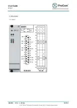
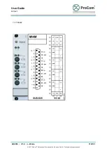
Страница 107: ...User Guide DVS 21 02 2018 V 1 0 L Wolle 107 131 2017 ProCom Professional Communication Service GmbH Technical changes reserved 11 Attachment 11 1 SV01...
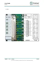
Страница 108: ...User Guide DVS 21 02 2018 V 1 0 L Wolle 108 131 2017 ProCom Professional Communication Service GmbH Technical changes reserved 11 2 CPU...
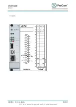
Страница 109: ...User Guide DVS 21 02 2018 V 1 0 L Wolle 109 131 2017 ProCom Professional Communication Service GmbH Technical changes reserved 11 3 LCPU...
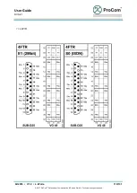
Страница 110: ...User Guide DVS 21 02 2018 V 1 0 L Wolle 110 131 2017 ProCom Professional Communication Service GmbH Technical changes reserved 11 4 4FTR...
Страница 111: ...User Guide DVS 21 02 2018 V 1 0 L Wolle 111 131 2017 ProCom Professional Communication Service GmbH Technical changes reserved...
Страница 112: ...User Guide DVS 21 02 2018 V 1 0 L Wolle 112 131 2017 ProCom Professional Communication Service GmbH Technical changes reserved 11 5 4NSA...
Страница 113: ...User Guide DVS 21 02 2018 V 1 0 L Wolle 113 131 2017 ProCom Professional Communication Service GmbH Technical changes reserved 11 6 4DAV...
Страница 114: ...User Guide DVS 21 02 2018 V 1 0 L Wolle 114 131 2017 ProCom Professional Communication Service GmbH Technical changes reserved 11 7 4NPA...
Страница 115: ...User Guide DVS 21 02 2018 V 1 0 L Wolle 115 131 2017 ProCom Professional Communication Service GmbH Technical changes reserved 11 8 4ZZA...
Страница 116: ...User Guide DVS 21 02 2018 V 1 0 L Wolle 116 131 2017 ProCom Professional Communication Service GmbH Technical changes reserved 11 9 4IOS...
Страница 117: ...User Guide DVS 21 02 2018 V 1 0 L Wolle 117 131 2017 ProCom Professional Communication Service GmbH Technical changes reserved 11 10 24LI...
Страница 118: ...User Guide DVS 21 02 2018 V 1 0 L Wolle 118 131 2017 ProCom Professional Communication Service GmbH Technical changes reserved 11 11 MI4M...
Страница 119: ...User Guide DVS 21 02 2018 V 1 0 L Wolle 119 131 2017 ProCom Professional Communication Service GmbH Technical changes reserved 11 12 USE1 RS232...
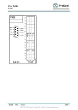
Страница 120: ...User Guide DVS 21 02 2018 V 1 0 L Wolle 120 131 2017 ProCom Professional Communication Service GmbH Technical changes reserved 11 13 V100...
Страница 121: ...User Guide DVS 21 02 2018 V 1 0 L Wolle 121 131 2017 ProCom Professional Communication Service GmbH Technical changes reserved...
Страница 122: ...User Guide DVS 21 02 2018 V 1 0 L Wolle 122 131 2017 ProCom Professional Communication Service GmbH Technical changes reserved 11 14 USE2...
Страница 123: ...User Guide DVS 21 02 2018 V 1 0 L Wolle 123 131 2017 ProCom Professional Communication Service GmbH Technical changes reserved...
Страница 124: ...User Guide DVS 21 02 2018 V 1 0 L Wolle 124 131 2017 ProCom Professional Communication Service GmbH Technical changes reserved...
Страница 125: ...User Guide DVS 21 02 2018 V 1 0 L Wolle 125 131 2017 ProCom Professional Communication Service GmbH Technical changes reserved 11 15 TG01...
Страница 126: ...User Guide DVS 21 02 2018 V 1 0 L Wolle 126 131 2017 ProCom Professional Communication Service GmbH Technical changes reserved 11 16 4LSL...
Страница 127: ...User Guide DVS 21 02 2018 V 1 0 L Wolle 127 131 2017 ProCom Professional Communication Service GmbH Technical changes reserved 11 17 4DSS...
Страница 128: ...User Guide DVS 21 02 2018 V 1 0 L Wolle 128 131 2017 ProCom Professional Communication Service GmbH Technical changes reserved 11 18 4DAE...
Страница 129: ...User Guide DVS 21 02 2018 V 1 0 L Wolle 129 131 2017 ProCom Professional Communication Service GmbH Technical changes reserved 11 19 Station Keypads DTA 12 48 66 84 114 WPS 04 AWC 06 4 10 16 22 28 34...
Страница 130: ...User Guide DVS 21 02 2018 V 1 0 L Wolle 130 131 2017 ProCom Professional Communication Service GmbH Technical changes reserved WPS 08 AWC 06 8 14 20 26 32 38 PMS PMK 16 16 32 48 64 80 96...
Страница 131: ...User Guide DVS 21 02 2018 V 1 0 L Wolle 131 131 2017 ProCom Professional Communication Service GmbH Technical changes reserved DTA LAN 24 78 132 186 240...