Maintenance Manual V001
FRECCIA
Maintenance Manual V001
FRECCIA
Seite 26
Seite 27
2.16. ELECTRICAL SYSTEM
The aircraft is equipped with a 12-volt, direct-current electrical system with grounded negative
pole.
The primary source of electrical energy is provided by the engine mounted interior alternator/ge-
nerator with total power of 750 W.
The internal alternator located at the rear of the engine block will charge the battery up to 13.5
VDC.
Power is supplied to the electrical and avionics circuits through a main bus bar located behind
instrument panel, this bus bar is energized anytime the Main switch is ON.
Each system is protected by circuit breaker which is permanently on. If some circuit is overloaded,
then the circuit breaker disconnects that circuit.
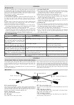
ELECTRICAL SYSTEM
FUSES
Start Armed
2 A
Fuel Pump
2 A
EFIS
3 A
Flap
3 A
Trim
1 A
2.17. ENGINE – ROTAX 912 ULS
For engine inspection and maintenance refer to original Rotax manuals supplied with the aircraft:
■
Operator´s Manual for ROTAX engine Type 912 Series
■
Documentation for ROTAX aircraft engines (CD – ROM)
■
Service instruction fur ROTAX Type 912 und 914 (series)
■
ROTAX service letter Warranty conditions for ROTAX engine types 912 and 914 (series)
■
ROTAX engine Log book
Engine removal, installation and replacement can only be done by Pro.Mecc authorized
service center.
ENGINE CONTROL
On the central control panel, in the middle of the cockpit there are the handgrips relative to:
■
Throttle lever
■
Choke push pull cable
The power levers and the choke one are fixed to a control box made of carbon fibre and they are
linked to steel-sheath cables.
The cables, fastened to the fuselage structure, pass the firewall and inside engine compartment
are fixed to a box that has the function to double the controls in order to reach the throttle lever
and the choke lever of the two engine carburetors.
ENGINE CONTROL
Control box
Quick draw
Control-engine cable
Sheath
Fuel lever
Lever
Adjustment of engine control
The engine-control lever must move with a right effort. In case of effort’s weakening, in flight the
lever could move ahead spontaneously and the engine’s power setting would increase. In this
case, adjust the engine choke lever. Loosen the M8 nut, lock it with a proper spanner and secure;
consequently, the friction increases and the engine’s control lever remain in a more appropriate
position.
Содержание Freccia
Страница 1: ...MAINTENANCE MANUAL UL AIRCRAFT LTF UL 2003 Manufacturer No FRXXX Registration No D MXXX ...
Страница 27: ......


