background image

Chapter 4  Data Transfer

4-7

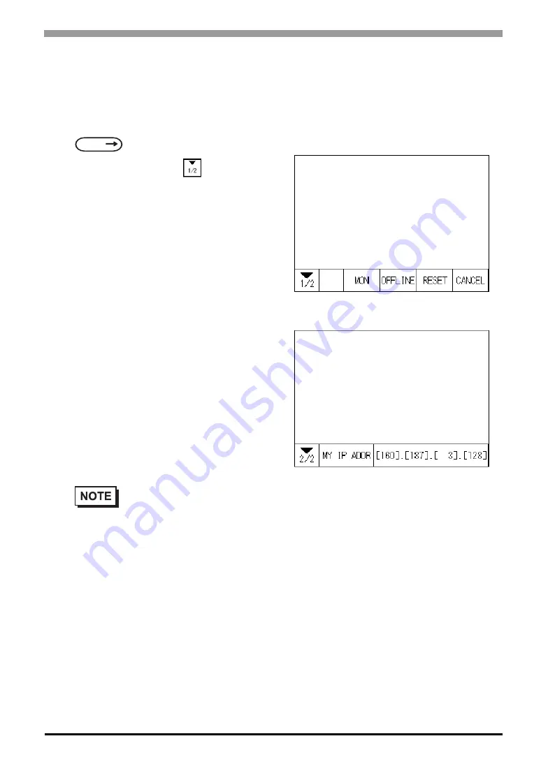
Checking the IP Address

Use the following procedure to check the IP Address assigned to the ST and some consideration/precautions.

1) Display the menu bar. For instructions on how to display the menu bar,

2) Click on the left-side 

cell of the menu bar 

to display the next menu.

3) The IP Address assigned to the ST will appear 

in the menu bar.

SEE

6.4.3 Set Up Touch Panel (page 6-13)

The IP Address will not be reflected unless ST was reset or power cord was reconnected. After 

changing “Ethernet Setup” settings, the ST must then be reset or power cord must be recon-

nected.

Содержание Pro-face ST Series

Страница 1: ...User Manual ST Series...

Страница 2: ...orporation All rights reserved All Company Manufacturer names used in this manual are the registered trademarks of those companies Note 1 It is forbidden to copy the contents of this manual in whole o...

Страница 3: ...sing limit switches etc to detect incorrect device movement To prevent accidents related to incorrect signal output or operation design all switches used to control vital machine operations so they ar...

Страница 4: ...occur If your ST s backlight suddenly turns OFF use the following steps to determine if the backlight is actually burned out 1 If your ST is not set to Standby Mode and the screen has gone blank your...

Страница 5: ...take apart the ST otherwise an electrical shock can occur Do not modify the ST unit Doing so may cause a fire or an electric shock Do not use the ST in an environment where flammable gasses are presen...

Страница 6: ...T malfunction Be careful that metal filings and wiring debris do not fall inside the ST since they can cause a fire ST malfunction or incorrect unit operation The liquid crystal panel contains a power...

Страница 7: ...vibration can occur Do not store or use the ST where chemicals such as organic solvents etc and acids can evaporate or where chemi cals and acids are present in the air Corrosive chemicals Acids alka...

Страница 8: ...ST s Stand by Mode which automatically turns the screen OFF when there is no input for a specified period of time Write FFFh to the System Data Area s Screen Display Off address 2 to turn the screen d...

Страница 9: ...re installed This unit has been carefully packed with special attention to quality However should you find anything damaged or missing please contact your local ST distributor immediately for prompt s...

Страница 10: ...ast 100 mm away from any other adjacent structures or machine parts If these conditions are not met the heat generated by the ST unit internal components may cause it to fail to meet UL standards The...

Страница 11: ...off TOOL port is for system set up and diagnostics in a nonhazardous location area only CE Marking Notes The ST400 AG41 24V ST401 AG41 24V ST402 AG41 24Vand ST403 AG41 24V are CE marked products that...

Страница 12: ...tor software version 6 30 or higher For information on how to confirm the version refer to the GP PRO PB for Windows Operation Manual which is supplied with the screen editor software PLC Abbreviation...

Страница 13: ...12 Memo...

Страница 14: ...ions 2 2 2 1 1 Electrical 2 2 2 1 2 Environmental 2 2 2 1 3 Structural 2 3 2 2 Functional Specifications 2 4 2 2 1 Display 2 4 2 2 2 Memory 2 5 2 2 3 Touch Panel and Clock 2 5 2 2 4 Touch Panel and Fu...

Страница 15: ...the Power Cord 5 2 5 1 2 From the Menu Bar 5 3 5 2 OFFLINE Mode Main Menu 5 4 5 3 Initialization 5 5 5 4 Self Diagnosis 5 7 CHAPTER 6 Initializing the ST 6 1 Initialization Screen 6 2 6 2 Initializat...

Страница 16: ...f Diagnosis Item List 7 4 7 2 2 Self Diagnosis Details 7 5 7 3 Troubleshooting 7 8 7 3 1 Possible Types of Trouble 7 8 7 3 2 No Display 7 9 7 3 3 No ST Host Communication 7 11 7 3 4 Touch Panel Does N...

Страница 17: ...16 CHAPTER 8 Maintenance 8 1 Regular Cleaning 8 2 8 1 1 Cleaning the Display 8 2 8 1 2 Installation Gasket Check Replacement 8 2 8 2 Periodic Check Points 8 4 8 3 Changing the Backlight 8 4 Index...

Страница 18: ...1 1 1 Introduction 1 1 Prior to Operating the ST 1 2 System Design 1 3 Accessories...

Страница 19: ...en Data Transfer the data from the Screen editor software on your PC to the ST unit using the Data Transfer Cable 5 GP Host Connection Set up the ST so that it can receive data from the Host PLC 6 Con...

Страница 20: ...III for Windows Device PLC Connection Manual included with the screen editor software SEE Recommended Units Page 1 8 SEE GP PRO PBIII for Windows Operation Manual included with the screen editor softw...

Страница 21: ...uded with the screen editor software SEE Recommended Units Page 1 8 SEE GP PRO PBIII for Windows Operation Manual included with the screen editor software SEE GP PRO PBIII for Windows Device PLC Conne...

Страница 22: ...For details about connecting SEE GP PRO PBIII for Windows Device PLC Connection Manual included with the screen editor software SEE Recommended Units Page 1 8 SEE GP PRO PBIII for Windows Operation Ma...

Страница 23: ...B03 RS232C Cable 2 CA3 CBL232 5M 01 Concentrator Hub Conventional Products PC Commercial Products General purpose Computer of PLC series or PLC etc Pro Server with Pro Studio Mitsubishi GPP Function S...

Страница 24: ...r Windows Device PLC Connection Manual included with the screen editor software SEE GP PRO PBIII for Windows Device PLC Connection Manual included with the screen editor software SEE GP PRO PBIII for...

Страница 25: ...et Touch Scanner Read Width 100mm Tohken TCD 5510M Touch Scanner Read Width 65mm TCD 5510L Touch Scanner Read Width 82mm TCD 5510W Touch Scanner Read Width 105mm NEC Infrontia BCK5435 STA Touch Scanne...

Страница 26: ...r Cable USB type GPW CB03 Product Name Model No Description RS 232C cable 1 CA CBL232 5M 01 5m Interface cables between the host PLC and the ST RS 422 cable 1 CA CBL422 5M 01 5m Mitsubishi FX Series C...

Страница 27: ...s screen The ST s touch panel can be operated with this cover sheet attached 5 sheets set Attachment CA4 ATMST 01 When replacing from GP 230 250 270 Series can be the spacer for the panel face cleara...

Страница 28: ...2 1 2 Specifications 2 1 General Specifications 2 2 Functional Specifications 2 3 Interface Specifications 2 4 Part Names and Functions 2 5 Dimensions...

Страница 29: ...rns to nor mal the normal display will be restored The ST s operation will not be affected even though the display is blurred Storage Temperature 20 C to 60 C Operating Humidity 10 RH to 90 RH Non con...

Страница 30: ...o confirm the type of conditions that will be present in the ST s operating environment If the installation gasket is used for a long period of time or if the unit and its gasket are removed from the...

Страница 31: ...50 000 hrs half of original brightness Color Red 2 Service life Ave 10 000 hrs half of original brightness Contrast Adjustment 8 levels of adjustment available via touch panel Brightness Adjustment 2...

Страница 32: ...ully charged battery Approximately 6 days with a 10 charged battery Clock Accuracy 65 seconds month at room temperature The ST s internal clock has a slight error At normal operating temperatures and...

Страница 33: ...nnector TOOL Asynchronous TTL level nonprocedural command I F During screen file development Used for transferring data to and from the GP application software and the ST During Operation Used for dat...

Страница 34: ...7 or 8 bits Stop Bit 1 or 2 bits Parity None Odd or Even Data Transmission Speed 2 400bps to 115 200bps Tool Connector TOOL Asynchronous TTL level nonprocedural command I F During screen file develop...

Страница 35: ...ERA Enable receive A Output 5 SG Ground 6 CSB Clear send B Input 7 SDB Send data B Output 8 CSA Clear send A Input 9 ERB Enable receive B Output RS 422 4 wire or 2 wire can be used to connect the ST...

Страница 36: ...on 2 NC No connection 3 LINE Line In Output 4 RTS Request Send Output 5 SG Ground 6 5V 5V External Output 2 2 When providing power via the Seimens Corporation Profibus connector power cannot be connec...

Страница 37: ...d 6 CSB Clear send B Input 7 SDB Send data B Output 8 CSA Clear send A Input 9 ERB Enable receive B Output This communication port is used exclusively for Extended SIO Scripts To use this port an Exte...

Страница 38: ...No Signal Signal Name Direction 1 CD RDA Carrier detect Receive data A Input Inpu 2 RD RDB Receive data Receive data B Input Input 3 SD SDA Send data Send data A Output Output 4 ER ERA Enable receive...

Страница 39: ...Bottom E I H C D A B Front F1 F1 F2 F2 F3 F3 F4 F4 F5 F5 F6 F6 ST403 AG41 24V Bottom J K E A Display B Touch Panel C Function Switch F1 to F6 D Power Lamp E Power Plug F RS 422 Interface X G RS 232C...

Страница 40: ...asteners 118 4 65 118 4 65 Top Top Front Front Right Side Right Side 104 4 09 104 4 09 5 0 20 5 0 20 41 1 61 41 1 61 Unit mm in Unit mm in 130 5 12 130 5 12 92 3 62 92 3 62 F1 F1 F2 F2 F3 F3 F4 F4 F5...

Страница 41: ...User s Manual 2 14 2 5 2 Panel Cut Dimensions 2 5 3 Installation Fasteners Unit mm in 118 5 1 0 4 67 0 04 0 92 5 1 3 64 1 0 0 Under 4 R3 F1 F2 F3 F4 F5 F6 11 0 43 16 0 63 10 0 39 31 1 22 M6 16 6 0 65...

Страница 42: ...3 1 3 Installation and Wiring 3 1 Installation 3 2 Wiring Precautions 3 3 Tool Connector 3 4 Ethernet Cable Connector...

Страница 43: ...et Check Replacement Page 8 2 Before installing the ST into a cabinet or panel check that the installation gasket is securely attached to the unit A gasket which has been used for a long period of tim...

Страница 44: ...jagged edges Also if desired metal reinforcing strips can be attached to the inside of the panel near the Panel Cut to increase the panel s strength Panel thickness should be from 1 6mm 0 06in to 10m...

Страница 45: ...Be sure that heat from surrounding equipment does not cause the ST to exceed its standard operating temperature When installing the ST in a slanted panel the panel face should not incline more than 30...

Страница 46: ...rs into the ST s insertion slots on the right and left side of the unit Be sure to insert installation fasteners in the recessed portion of a installation fas teners hole Refer to the following figure...

Страница 47: ...eners are made to slide to a back side 4 Use a Phillips screwdriver to tighten each fastener screw and secure the ST in place A torque of only 0 5 N m is sufficient to tighten these screws Do not use...

Страница 48: ...aker type power switch to the ST s power cord Be sure to ground the ST s FG terminal Failure to do so can lead to an electrical shock or ST malfunction If the power cord is pulled strongly the power p...

Страница 49: ...e power plug Power Cord Specifications Power Cord Diameter 0 2 to 2 5 mm2 0 0001 to 0 0097 inch2 24 to 12 AWG Conductor Type Simple or Twisted Wire Conductor Length If the Conductor s end individual w...

Страница 50: ...To avoid excess noise make the power cord as short as possible Use flat screwriver SIZE 0 6 x 3 5 to tighten the terminal block wire set screws The torque required to tighten these screws is 0 5 to 0...

Страница 51: ...and FG Frame Ground terminal are con nected to each other When connecting the SG line to another device be sure that the design of the system connection does not produce a shorting loop The grounding...

Страница 52: ...fer Cable Memory Loader or the Bar Code Reader can be attached to the ST unit s Tool Connector When the Bar Code Reader uses a separate power supply Turn the Bar Code Reader ON before turning the ST O...

Страница 53: ...atible and transmits data at 10Mbps The Ethernet I F is equipped on only the ST It is strongly recommended that your Ethernet network is installed by a trained engineer 1 1 connections using a cross c...

Страница 54: ...4 1 4 Data Transfer 4 1 Serial Data Transfer 4 2 Ethernet Data Transfer...

Страница 55: ...ec tor when you install the cable The main body and the connector might break down Pro face s transfer cable GPW CB02 is sold separately The transfer cable package does not include the PC s interface...

Страница 56: ...ble and then turn the ST ON The Initial Start Mode screen will appear on the ST and you can transfer screen from your PC The screen will change to the Trans fer screen automatically USB transfer cable...

Страница 57: ...the ST after data transfer the OFFLINE mode s Main Menu will appear If you do NOT set up the ST the screen designated in INITIAL SETTINGS SCREEN SETUP INITIAL SCREEN FILE NO will appear and the scree...

Страница 58: ...nd data 1 When the settings in the Ethernet Setup screen are not specified and data is sent the ST unit s factory set IP Address settings are used If you choose to use the factory set IP address be su...

Страница 59: ...to manually change the ST screen to Ethernet Mode via the following screen You can now transfer data from your PC s screen editor software How to transfer data using a previously set IP address 2 When...

Страница 60: ...ns on how to display the menu bar 2 Click on the left side cell of the menu bar to display the next menu 3 The IP Address assigned to the ST will appear in the menu bar SEE 6 4 3 Set Up Touch Panel pa...

Страница 61: ...ST Series User s Manual 4 8 Memo...

Страница 62: ...5 1 5 OFFLINE Mode 5 1 Entering OFFLINE Mode 5 2 OFFLINE Mode Main Menu 5 3 Initialization 5 4 Self Diagnosis...

Страница 63: ...is etc It is possible to enter an offline mode by the following two methods 5 1 1 After Plugging in the Power Cord Touch the upper left hand corner of the ST screen within 10 seconds of plugging in th...

Страница 64: ...ng the OFFLINE mode the following screen appears Here enter the password then touch Set to enter OFFLINE mode When Passwords setting For more information about ENTERING NUMBER SEE 6 4 3 Set Up Touch P...

Страница 65: ...m the screen editor software SELF DIAGNOSIS Checks to see if there are any problems with the ST System or Interface I F RUN Starts ST operation LANGUAGE CHANGEOVER FUNCTION When in Japanese display mo...

Страница 66: ...g it use the numeric touch keys located at the bottom of the screen to enter numeric values After inputting each value touch the SET key to define the value Selecting Setup Conditions After selecting...

Страница 67: ...elay in return ing to the previous screen Therefore do not touch the screen until the previous menu display returns Press the SET key to write the Setup conditions onto the Internal FEPROM and Press t...

Страница 68: ...eys may appear at different times at the top of the screen SET Key When this key is pressed your selected Self Diagnosis test begins ESC Key When this key is pressed the selected Self Diagnosis test i...

Страница 69: ...the lower left corner of the displayed screen 1 and the lower right corner 2 Return To Main Menu Touch the MAIN Key in the top right corner of the SELF DIAGNOSIS menu to return to the MAIN MENU When...

Страница 70: ...itializing the ST 6 1 Initialization Screen 6 2 Initialization Items 6 3 System Environment Setup 6 4 Set Up I O 6 5 PLC Setup 6 6 Initialize Internal Memory 6 7 Set Up Time 6 8 Set Up Screen 6 9 Font...

Страница 71: ...ted with a single 1 PLC n 1 Multiple STs are connected with a single PLC The STs successively pass a PLC Access Token exclu sive PLC interaction key among themselves to designate which unit can commun...

Страница 72: ...the Device PLC type selected the screens that appear in your screen editor soft ware will vary SEE 5 OFFLINE Mode Page 5 1 SYSTEM ENVIRONMENT SETUP SYSTEM SETUP System Area SETUP Global Window CHAR ST...

Страница 73: ...the screen is cleared after the ST s standard default time elapses When SYSTEM DATA AREA s SCREEN DISPLAY OFF 1 data is 0000h and the following operations are not performed on the screen for the User...

Страница 74: ...re available for BCD format 6 3 2 System Area Setup SYSTEM AREA SETUP is necessary for the PLC to control its ST related data and prepares the PLC inter nal Data Memory DM and Data Register D 1 Use th...

Страница 75: ...tion process follows this formula System Data Start Address n For example if the System Area Start Address was D00200 and the Change Screen Number option had been selected if you refer to the System A...

Страница 76: ...ns are fixed to the values entered here When set to Indirect the WINDOW REG NO s word address as prepared in the System Area is a variable This means it can have the REGISTRATION NO written to it and...

Страница 77: ...own below and setup the CHARACTER STRING DATA MODE I Data Device Storage Order II Internal Word Byte LH HL Storage Order III Internal Double word Word LH HL Storage Order Character String Data Mode Li...

Страница 78: ...C D E g Characters 16 bit Device LH Order D0100 D0101 32 bit Device LH Orde D0100 16 bit Device HLOrder D0100 D0101 32 bit Device HLOrder D0100 A B C D E F G H I J E g Characters 16 bit Device LH Orde...

Страница 79: ...LC Device When there are nine characters they are arranged as shown below 32 bit Devices ST stores the character string from the start as groups of 4 into1 PLC Device When there are nine characters th...

Страница 80: ...match the settings listed below with the SIO setup on the PLC host if not an error may occur SEE GP PRO PBIII for Windows Device PLC Connection Manual included with the screen editor soft ware GP PRO...

Страница 81: ...ER CONTRL COMMUNICATION INTERFACE These settings are used for data communication When using the ST400 unit select either RS 422 2 wire or RS 422 4 wire When using the ST401 unit the data communicatio...

Страница 82: ...e PLC the number of times set by this option The default is 2 6 4 3 Set Up Touch Panel Touch operation and Force Reset setup and Display Device adjustments are made here There may be dif frences on th...

Страница 83: ...INE CONTRAST ADJUSTMENT When this option is set ON CONTRAST ADJUSTMENTs can be made through touch input While pressing the upper right hand corner 1 of the screen press the upper left corner 2 to ente...

Страница 84: ...in the middle of RUN mode PLC ST communication Regardless of a normal and reversed display the left side of the contrast adjustment bar displayed at the bottom area of the screen is always Bright Wit...

Страница 85: ...comes high and its current brightness level is set to low this effect may be more pronounced This phenomenon is however a common attribute of LCDs and is not a defect To solve this use this setting fo...

Страница 86: ...and the device connected to the Expansion Serial Interface The supported communication rates vary depending on the connected device Refer to the instruction manual of the connected device for more in...

Страница 87: ...s Manual 6 18 6 4 7 Expansion Serial Environment Setup Can only display the setting data entered in the screen editor software This data cannot be changed 6 4 8 COMMUNICATION PORT SETUP This feature i...

Страница 88: ...h ST connected to the PLC SYSTEM AREA START DEV START ADR Setup the System Data Area s Start Address Device addresses that can be allocated will differ depending on the type of PLC used The screens th...

Страница 89: ...RMATION DEV ADR In the n 1 multi link connection the Network Information uses 2 words in its correspondences These two 2 words consist of a Connection List and a Validation List described later in thi...

Страница 90: ...t is written to the Validation List For example the value 002D h in the Connection List setup as the 0 bit 2 bit 3 bit and 5 bit writes to the Validation List The word address for the Connection List...

Страница 91: ...esult the ST will com mand better touch panel numeric input and switch response times Leaving the ST in this mode does not drastically influence the touch panel operation response time of other STs Th...

Страница 92: ...nel operations are performed The Monopolize process begins when the System Data Area s 7th bit of word address LS14 turns ON and ends either when the bit turns OFF or when the time set here elapses Fo...

Страница 93: ...ver Port No using a value from 1025 to 65526 Starting from the value entered here a total of 10 consecutive ports can be used The default setting is 8000 Enter the ETHERNET SETUP settings after receiv...

Страница 94: ...e settings are not necessary Only ST unit HOST IP ADDRESS Sets up the IP address of the host computer where the 2 Way driver s operation logs will be output FACILITY 0 23 Sets up the facility OUTPUT L...

Страница 95: ...d to the 2 Way driver operation occurs 6 5 7 Self Diagnosis Runs the Self Diagnosis program for the Ethernet operation The ST must be connected to the Ethernet net work prior to running this program O...

Страница 96: ...ernal memory enter the common password 1101 or the password entered in the SYS TEM SET UP screen For details about entering password numeric values You cannot cancel the Initialization procedure after...

Страница 97: ...ght error At normal operating temperatures and conditions with the ST operating from its lithium battery the degree of error is 65 seconds per month Variations in operating conditions and battery life...

Страница 98: ...en file number that will display first upon powering up If the BIN option for DATA TYPE OF SCREEN NO in SYSTEM SET UP had been selected enter a number from 1 to 8999 Or if BCD was the option set up th...

Страница 99: ...re displayed as 16x8 dot characters Full size characters regardless of the display size used will always be displayed as 16x16 dot characters When enlarged this font will stay as 16x16 dot character H...

Страница 100: ...7 1 7 RUN Mode and Errors 7 1 RUN Mode 7 2 Self Diagnosis 7 3 Troubleshooting 7 4 Error Messages 7 5 Error Message Details...

Страница 101: ...any value other than 0 In this case when the ST s power cord is connected the following version information screen will appear In the top right corner of the screen a value will appear and count down...

Страница 102: ...with the PLC begins If however the designated initial screen has not been created or does not exist the above display will remain E g To enter OFFLINE Mode simply touch the top left corner of the ST...

Страница 103: ...he System and Protocol of the ST Internal Memory FEPROM Checks the internal display memory Frame Buffer Checks the Tool Connector control lines and send receive lines 1 Checks the Input Port for Digit...

Страница 104: ...IROM CHECKSUM is normal OK displays if there is a problem NG displays TOUCH PANEL Touch Panel check Checks if each touch cell highlights when pressed INTERNAL FEPROM CHECKSUM System Protocol The Inter...

Страница 105: ...intenance SIO CHECK Checks the RS 232C and RS 422 SIO lines for areas where communication problems develop In the menu select which check to run To run the check connecting the SIO cable is necessary...

Страница 106: ...eck you must connect the SIO cable If all is normal the message OK appears If there is a problem an error message appears Only ST402 unit have this feature The SIO cable wiring is as shown below FUNCT...

Страница 107: ...s to the OFFLINE mode unexpectedly while operating or the ST automatically goes to the OFFLINE mode when the power is turned ON 5 Clock Settings Cannot be Entered Even after clock settings are entered...

Страница 108: ...Lamp light turn ON Is it using the correct rated voltage Unplug the ST s power cord Disconnect the SIO and AUX cable Is the power cable connected properly to this unit Does turning ON the power one mo...

Страница 109: ...K Has Display Off data been written to the SYSTEM DATA AREA Has Backlight Off data been written to the SYSTEM DATA AREA There is a problem with the Backlight or ST unit Please contact your local ST di...

Страница 110: ...PLC Is the SIO cable attached properly to this unit Attach the SIO cable unit properly making sure all connections are secure Is the Termination Resistor correctly installed Install the Termination R...

Страница 111: ...data and correct the setup values Tag Reference Manual included with the screen creation software YES YES NO NO Are the corresponding SIO INITIALIZE settings OK Enter correct settings and values 6 In...

Страница 112: ...hOperationMode 6InitializingtheST page6 1 Disconnect all the cables including SIO cable and AUX cable except the Power cable RunSELF DIAGNOSIS TOUCHPANELCHECKto seetheSTisOK Are the settings for touch...

Страница 113: ...sfer Force System Setup again Buzzer Sound Timing Reason Solution Continous beep approx 1 sec intervals When power to the ST is turned ON The ST s system program is destroyed Send the correct ST sys t...

Страница 114: ...connect the communication cable correctly PLC NOT RESPONDING 02 FE PLC s power is not turned ON Turn ON the PLC s power ST unit INITIALIZE settings Setup I O PLC Setting are incorrect Check the INITIA...

Страница 115: ...TRANSFER ERROR An error occurred in the data trans mission from the screen editor to the STpanel Re transfer the screen data SCREEN TAG LIMIT EXCEEDED Tags are setup beyond the tag limit max of 385 7...

Страница 116: ...ed during screen data transfer Possible Solutions Check if the ST s Power Cord and the Input signal line have been wired separately from each other Check that the FG line has been grounded correctly a...

Страница 117: ...e and the commu nication line wiring and FG grounding are correct Screen Data or Project Data Related Problems If an error seems to be caused by a particular ST operation the error may be related to t...

Страница 118: ...0C2 194 All or part of the System Data Area address A tag or S tag address range overlap the addresses setup in a T tag 1 195 196 0C3 197 All or part of a T tag 1 S tag or K tag address range overlap...

Страница 119: ...ange of the System Data Area 0 to 2047 and re send correct data When using a Toyoda Machine Works PLC Set the addresses within the set range of the devices When using a Yaskawa PLC Set the addresses w...

Страница 120: ...f 1 byte codes E g When the Display Error Number is 8 or 5 use only the left column as the error number In Toshiba s PROSEC T Series the Error Code is 4 characters long on the ST Error Numbers are cha...

Страница 121: ...displayed when D Scripts and Global D Scripts are not configured properly The ST Series unit displays the error message on the bottom at the ST screen The following table lists the numbers assigned to...

Страница 122: ...ssage Extended SIO Script Extended SIO Script Error No Description 001 The total number of the Functions of Extended SIO Scripts exceeds the limit The maximum number of Functions of Extended SIO Scrip...

Страница 123: ...ST Series User s Manual 7 24 Memo...

Страница 124: ...8 1 8 Maintenance 8 1 Regular Cleaning 8 2 Periodic Check Points 8 3 Changing the Backlight...

Страница 125: ...placement Procedure 1 Place the ST on a flat level surface with the display facing downwards 2 Remove the old gasket from the ST Do not use paint thinner organic solvents or a strong acid compound to...

Страница 126: ...5 Be sure the gasket s seam is not inserted into any of the unit s corners only in the straight sections of the groove Inserting it into a corner may lead to its even tually tearing To ensure the inst...

Страница 127: ...re of 39o C or less Is the operating atmosphere free of corrosive gasses Electrical Specifications Is the input voltage appropriate DC19 2V to DC28 8V Related Items Are all power cords and cables conn...

Страница 128: ...F 7 4 Checks the System and Protocol of the ST Internal Mem ory 7 4 Checks the Tool Connector control lines and send receive lines 7 4 Cleaning the Display 8 2 Clock Accuracy 2 5 Clock Settings Canno...

Страница 129: ...ialization 5 5 Initialization Items 6 3 Initialization Screen 6 2 INITIALIZE 5 4 Initialize Internal Memory 6 27 INITIALIZE MEMORY 6 3 Initialize ST Memory 6 27 Initializing the ST 6 1 INPUT PORT 7 6...

Страница 130: ...8 Return To Previous Screen 5 6 Revision Information 10 RI VCC 6 17 RS 232C cable 1 9 RS 422 cable 1 9 RUN 5 4 RUN Mode 7 1 7 2 S Safety Icons 2 Screen 1 9 SCREEN DATA TRANSFER 5 4 Screen Data Transf...

Страница 131: ...4 System Setup 6 4 T Text 2 4 Tool Connector 1 9 2 12 3 11 TOOL CONNECTOR LOOP BACK 7 6 TOUCH BUZZER SOUND 6 5 TOUCH OPERATION MODE 6 13 TOUCH PANEL 7 5 Touch Panel 3 2 5 2 12 Touch Panel Does Not Res...

Отзывы: