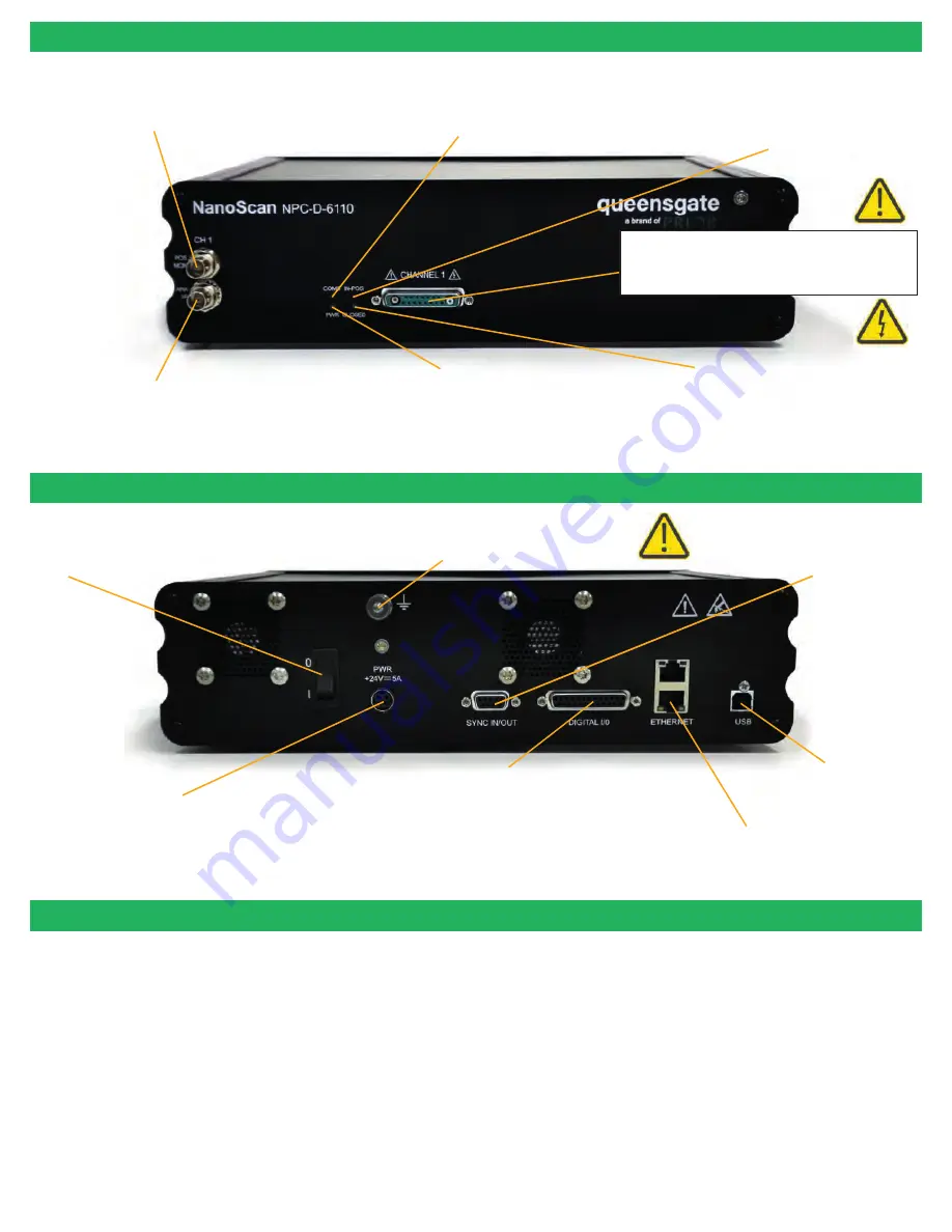
CONNECTING YOUR SYSTEM - FRONT OF UNIT
POS MON connector
Analogue position monitor output
BNC connector(s)
S
ingle ended output(s).
ANA I/P connector
Signal used to control the stage position
Analogue command input
BNC connector(s)
Si
ngle ended input(s).
On/Off switch
Earth Stud - M4 threaded stud
Provides additionalground t
o
reduce interference of background
electrical noise. Do not raise above 0V ground potential
P
WR
Connector
Provides power to the
controller electronics.
4 pin mini-DIN with screen Input
+24V dc ±0.75V @ 5A
ONLY connect an approved power supply.
Digital I/O Connector.
Provides digital inputs and outputs for interfacing controller to
external equipment.
TRIG inputs and outputs
IN_POS Output
Stepped input and outputs
25 pin D-type socket; 5V TTL input/output
MUST use shielded cable.
Ethernet Connector
for upgrading firmware
USB Type B
connector
Used to communicate with
an external computer.
SYNC IN/OUT connector provides
RS232C connection with connected
computer using supplied gender
changing adapt
e
r.
Power Indicator LED
Indicates the power status a
nd controller ready
RED steady = Controller configuring/not ready (can take up
to 30 seconds).
GREEN steady = Controller powered and ready for
operation
CLOSED INDICATOR LED
Indicates the status of the stage control Loop
OFF = Stage NOT connected
ORANGE = Stage settings being loaded on connection
RED = Controller operating in OPEN loop mode
GREEN = Controller operating in CLOSED loop mode
YELLOW = Controller servo output frozen
COMS Indicator LED
Indicates the sta
tus of
communications with the
connected computer.
Not lit = No communications taking place.
GREEN lit or flashing =
c
ommunications
active
IN POS Indicator LED
Indicates the status of the stage position in CLOSED
loop mode.
OFF = Stage has not reached the desired position.
ORANGE = Stage settings being loaded on connection.
GREEN = Stage has reached the desired position
Nano Mechanism Connector – connect the
S
P400
to
this position.
NOTE
:
High Voltage present on connector – up to
160VDC
CONNECTING YOUR SYSTEM - BACK OF UNIT
TURNING ON YOUR SYSTEM
1.
Once the stage is mounted, connect stage to the controller ensuring that the connector screws are tightened to the controller
lock posts. The
stage must be mounted to a flat surface before being powered.
On power-up the controller will always
move
the stage across its range to carry out autocalibration. It is important to ensure that
there is sufficient clearance
between the lens, sample and illumination to allow this to take place.
If the temperature or load changes significantly the
stage can clip at one end of the travel. Should this happen restart your system to allow auto-calibration
; this rebalances the
stage so that the closed loop range is cent
e
red within the open loop range.
2.
Connect Power to
the
controller
and/or USB as required.
3.
Switch ON controller using switch on rear panel. After approx. 30 seconds, the relevant stage channel should show two green
lights (C
LOSED
and IN-POS). This indicates the stage is operating in the CLOSED loop mode and IN-POS LED indicates stage
has
reached position within a
pre-defined band.
4.
The analogue input and POS MON output is 0V to +10V giving a scale factor of 40µ
m
/volt
for the SP400 and 60µ/volt for the
SP600
. The
analogue input is enabled by
default.
5.
The system has 8 memory positions for PID settling (
accessible via the USB interface
). The system has been shipped with
two
optimized settings . The default setting has been optimized for loads from
150g to 500g
for use with an incubator, it is possible to
switch to a fast
setting for loads up to 350g.
Do not use the fast setting with an incubator or load
s
over 350g as damage may
occur.
To c
hang
e
to other settings
it
is necessary to connect to a computer,
described
in
the
software
section
below.
Remove input commands. If still vibrating please contact Prior


