background image

33 


Network Configuration 

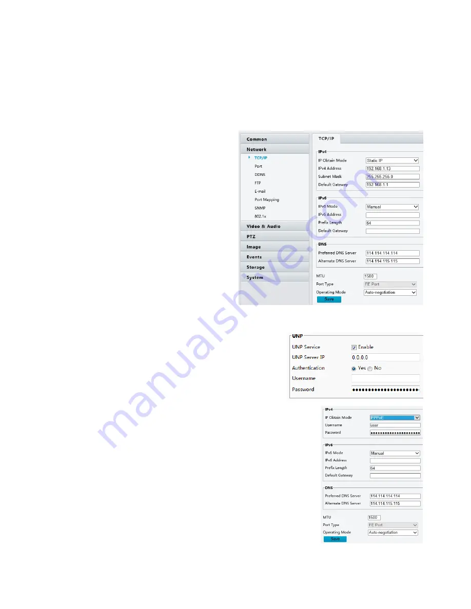
TCP/IP 

Modify communication settings such as the IP address for the camera so that the camera can communicate with 
other devices. 


NOTE: 


After you have changed the IP address, you need to use the new IP address to log in. 


The configurations of DNS (Domain Name System) server are applicable when the device is accessed by 
domain name. 


1.


Click 

Setup > Network > TCP/IP. 


2.


Select 

Static IP 

from the 

IP Obtain Mode 

drop-down list. 

3.


Enter the IP address, subnet mask, and default 
gateway address. Make sure that the IP address 
of the camera is unique in the network. 

4.


Click 

Save


If a gatekeeper or firewall is used in the network, Universal Network Passport (UNP) can be used to interconnect 
the network, and the UNP server will assign an IP address to the connected cameras. 

1.


Select Enable for UNP Service. 

2.


In the 

UNP Server IP 

text box, enter an IP address for the 

UNP server. Select 

Yes 

to enable authentication, and then 

set the username and password for UNP authentication. 

3.


Click 

Save


NOTE: 


This function is not supported by some models, please see the actual model 
for details. 

PPPoE 

If the camera is connected to the network through Point to Point Over Ethernet 
(PPPoE), you need to select PPPoE as the IP obtainment mode. 


1.


Click 

Setup > Network > TCP/IP

2.


Select 

PPPoE 

from the 

IP Obtain Mode 

drop-down list. 

3.


Enter the username and password provided by your internet Service 
Provider (ISP). 

4.


Click 

Save


NOTE: 


This function is not supported by some models, please see the actual 
model for details. 

DHCP 

The Dynamic Host Configuration Protocol (DHCP) is enabled by default when the camera is delivered. If a DHCP 
server is deployed in the network, the camera can automatically obtain an IP address from the DHCP server. 
To manually configure DHCP, follow the steps below: 

Содержание HD-PTZ9IP

Страница 1: ...1 PTZ Camera USER MANUAL Prestel HD PTZ9IP ...

Страница 2: ...EM MENU 21 21 OPERATION USING THE INFRARED REMOTE CONTROLLER 22 PAN TILT AND ZOOM OPERATION 22 OPERATING MULTIPLE CAMERAS WITH THE INFRARED REMOTE CONTROLLER 23 ADJUSTING THE CAMERA 23 STORING THE CAMERA SETTINGS IN MEMORY THEPRESETTINGFEATURE 24 MENU CONFIGURATION 25 DIMENSION 26 SPECIFICATIONS 27 PART TWO NETWORK CAMERA USER MANUAL 28 NETWORK CONNECTION 28 LOGIN 28 LOGGING IN TO THE WEB INTERFAC...

Страница 3: ...TENANCE 47 SECURITY 47 SETTING THE SYSTEM TIME 48 SETTING SERVERS 48 SERIAL PORT MODE CONFIGURATION 49 MAINTENANCE 52 UPGRADING THE DEVICE 52 RESTARTING THE SYSTEM 52 IMPORTING AND EXPORTING SYSTEM CONFIGURATION FILE 52 COLLECTING DIAGNOSTIC INFORMATION 53 DIGITAL ZOOM FOCUS CONFIGURATION 53 LIVE VIEW 54 LIVE VIEW TOOLBAR 54 VIEWING CERTAIN AREA OF IMAGES 55 USING 3D POSITIONING 55 VIDEO PLAYBACK ...

Страница 4: ... for any specific product In this manual the illustrations of displayed interface parameters displayed drawings and value ranges may vary with models Please see the actual product for details Due to uncertainties such as physical environment discrepancy may exist between the actual values and reference values provided in this manual Use of this document and the subsequent results shall be entirely...

Страница 5: ...ance FCC Part 15 This equipment has been tested and found to comply with the limits for digital device pursuant to part 15 of the FCC Rules These limits are designed to provide reasonable protection against harmful interference when the equipment is operated in a commercial environment This equipment generates uses and can radiate radio frequency energy and if not installed and used in accordance ...

Страница 6: ...6 WHAT S IN THE BOX Accessories Optional ...

Страница 7: ...DC 12V 350 degree continuous pan 120 degree continuous tilt 128 presets Speed up to 100 degrees sec Standard mounting and ceiling mounting with E Flip function IR remote control RS 232 control RS 422 485 control You can use the infrared remote controller to set the camera and also to select panning tilting and zooming from the setting menu You can store up to 6 presets of camera direction and came...

Страница 8: ...at selection 7 Audio Output 8 Audio Input 9 IR Remote ID Camera ID for IR remote controller 10 12V DC Power Port Connect the supplied AC power adaptor and cord 11 IR Remote Controller Sensors These are sensors to receive commands from infrared remote controller 12 Lens This is a 20X 30X magnification optical zoom lens 13 Power LED Indicator Turns green when the camera is connected to power outlet ...

Страница 9: ...ller 1 CAMERA SELECT 2 FOCUS Auto Far Near Manual 3 DATA SCREEN On screen menu display ON OFF 4 PAN TILT Pan and Tilt direction control HOME Home position Resolution reset 5 L R DIRECTION SET Left and right orientation setting 6 POWER 7 BACK LIGHT 8 PRESET POSITION 9 PAN TILT RESET 10 ZOOM IN OUT Slow T Slow W Fast T Fast W ...

Страница 10: ...in these third party components or accessories Notes Use only the AC power adaptor JEITA type4 supplied with the unit Do not use any other AC power adaptor Polarity of the plug Youhave to set the video format of the signal to output from the camera For detailed information on how to set the video format see SYSTEM SELECT switch on page 19 ...

Страница 11: ...u now have SDI video output 3 SDI video only supports 1080P IP Video Signal The camera can simultaneously stream IP video output and SDI video output and HDMI video output on video format 1080P25 and 1080P30 1 Connect the camera to the network using Cat5 Cat6 network cable 2 Set camera video format to 1080P25 or 1080P30 Refer to Page 16 20 3 PELCO address and Baud Rate setting on the camera has to...

Страница 12: ...era User Manual Use the Infrared Remote Controller To operate the camera from a short distance System Configuration A For IR remote control details refer to Operation Using the Infrared Remote Controller see page 21 Use RS 232 VISCA You can use RS 232 port to connect to optional controllers such as joystick control keyboard control PC station to operate the camera To perform pan tilt and zoom oper...

Страница 13: ...arty controller VISCA The controller must be VISCA compatible 6 Camera does not support Daisy Chain in RS232 control mode 7 You can make RS232 connection cable if you have the following applications Use RS 422 VISCA RS485 PELCO P D You can use RS 422 485 port connect to optional controllers such as joystick control keyboard control PC station to operate the camera To perform pan tilt and zoom oper...

Страница 14: ...fter the Bottom Dip Switch has been set upcorrectly 4 Does not need setting camera address in way of RS422 VISCA controlling 5 Use the RS422 control cable provided by third party controller The controller must be VISCAcompatible 6 Camera supports Daisy Chain connection up to 7 cameras 7 The connection of SONY keyboard is different than other VISCA None Sony keyboard SONY Keyboard RS422 Connection ...

Страница 15: ... not support daisy chain connection for using multiple cameras For control details refer to Operating Instructions of control keyboard station software You need to match the communication speed between the camera and the joystick controller You cannot use the RS 232 connections when using the RS422 485 connection Operating Multiple Cameras Using RS 422 485 Using RS 422 VISCA you can connect up to ...

Страница 16: ... the way of bottom DIP switch setting They override each other After the camera is turned on the camera takes the last setting before it is turned on either set through the OSD or bottom DIP switch The Bottom DIP Switch Settings Bit 1 3 Camera Address setting for PELCO protocol Bit 4 Video Output Video Color Space Bit 5 Reserve Bit 6 RS 232 RS 422 Bit 7 8 RS 232 RS 422 Baud Rate 1 Camera Address s...

Страница 17: ...e Numbers or the Letters The video format that the Number or Letter stands for refer to the video format as the chart following IR Remote Controller ID Setting Set the IR SELECT switch on the back panel of the camera to 1 2 or 3 which is the camera ID number that you want to operate on the Remote Controller Numbers Letters Video Resolution 0 1080i59 94 1 1080P29 97 2 720P59 94 3 1080P59 94 4 720P2...

Страница 18: ...Menu The name of the setting menu currently selected is displayed here 2 Selected Item Selectsasettingitem The selected item is shown by the cursor Move the cursor up or down by pressing the button on the infrared remote controller 3 Setting Items The setting items for this setting menu are displayed Select the setting item using the button on the infrared remote controller 4 Set Value The current...

Страница 19: ...Speed can be selected from the following 1 1 1 2 1 4 1 8 1 15 1 30 1 60 1 90 1 100 1 125 1 180 1 250 1 350 1 500 1 725 1 1000 1 1500 1 2000 1 3000 1 4000 1 6000 1 10K IRIS Select the iris the following CLOSE F14 F11 F9 6 F8 0 F6 8 F5 6 F4 8 F4 0 F3 4 F2 8 F2 4 F2 0 F1 6 LEVEL Select the brightness level from 0 5 to 31 EX COMP Exposure Compensation When MODE is set to one of FULL AUTO SHUTTER PRI o...

Страница 20: ...s and also controls the blown out highlights You can select the wide dynamic range mode between ON and OFF COLOR You can configure the color gain from 1 15 Use this setting when bright color is particularly important HUE You can adjust color phase from 1 15 Defog mode When the surrounding area of the subject is foggy and low contrast the defog mode will make the subject appear clearer When it is s...

Страница 21: ...n The camera goes to Home position when it is powered on or reset AUTO FOCUS Set speed of auto focusing from Low to Normal VIDEO FORMAT You can change the video format by adjusting this item Select the item press button to choose the video format you want to set to then press Pressing button changes value on some product models or HOME button to confirm it After you confirm your choice press HOME ...

Страница 22: ... camera toward the opposite direction from that of the button you pressed for example when you change the direction of the camera while checking the picture on the screen In such a case press the 2 REV button while holding down the L R DIRECTION SET button Arrow button Movement of the camera Setting While holding down Press To reset the setting To reset the setting press the 1 STD button while hol...

Страница 23: ...operate the camera s using the infrared remote controller the CAMERA SELECT button pressed in step 2 lights Adjusting the Camera Focusing on a Subject Focusing the camera on a subject automatically Press the AUTO button The camera focuses on the subject at the center of the screen automatically AUTO NEAR MANUAL BACK LIGHT Focusing the camera on a subject manually After pressing the MANUAL button p...

Страница 24: ...T RESET button to reset the pan tilt position 2 Adjust the position zooming focusing and backlighting of the camera WhileholdingdownthePRESET button pressanyof the POSITION buttons 1 to 6 in which you want to store the settings Recalling the stored settings Press any of the POSITION buttons 1 to 6 in which you have stored the settings Cancelling the preset memory While holding down the RESET butto...

Страница 25: ...25 Menu Configuration The menus of the camera are configured as described below For more details refer to the pages in parentheses The initial settings of each item are in bold ...

Страница 26: ...26 Dimension Unit mm ...

Страница 27: ...27 Specifications ...

Страница 28: ...ct the camera to power to start it After the camera is started you can access the camera from a PC client installed with a web browser or the video management software Internet Explorer IE is a recommended web browser Please contact your dealer to get the video management software Please refer to the user manual of video management software for detailed information The following takes IE on a Micr...

Страница 29: ... you access the camera follow the steps to set User Account Control Settings to Never notify Logging In to the Web Interface The default static IP address of the camera is 192 168 0 13 and the default subnet mask is 255 255 255 0 DHCP is turned on by default If a DHCP server is used in the network the IP address of your camera may be assigned dynamically and you need to use the correct IP address ...

Страница 30: ...enter the password each time when you log in To ensure security you are not advised to select Save Password To clear the Username and Password text boxes and the Save Password check box click Reset NOTE Important Be sure to keep the new password written down and put in a safe place If the password is forgotten camera will require hardware resetting Additional charges may apply for resetservices Fo...

Страница 31: ...fied For the actual settings see the Web interface It is recommended that you change the password when you are logged in the first time For details about how to change a password see Security Configuring Parameters Local Parameters Set local parameters for your PC NOTE The local parameters may vary with models please see the actual Web interface fordetails Select Setup to go into IP camera setting...

Страница 32: ...s it RGB32 is only supported by some low version graphic cards c Protocol i Set the protocol used to transmit media streams to be decoded by the PC B Record and Snapshot a Recording i Subsection By Time Duration of recorded video for each recording file on the computer For example 2minutes ii Subsection By Size Size of each recording file stored on the computer For example 5M b When Storage Full i...

Страница 33: ...1 Select Enable for UNP Service 2 In the UNP Server IP text box enter an IP address for the UNP server Select Yes to enable authentication and then set the username and password for UNPauthentication 3 Click Save NOTE This function is not supported by some models please see the actual model for details PPPoE If the camera is connected to the network through Point to Point Over Ethernet PPPoE you n...

Страница 34: ...hots from network cameras to the specified FTP server 1 Click Setup Network FTP 2 Configure the IP address port number of the FTP server the username and password of the upload account enable Upload Images and Overwrite Storage and then set the overwrite image threshold 3 Click Save ail After the configuration of E mail when alarms are triggered you will be able to send messages to the specified E...

Страница 35: ...external ports must be configured external IP is obtained automatically by the camera If the configured port is occupied then the Status will showInactive 3 Click Save DDNS 1 Click Setup Network DDNS 2 Enable DDNS Service 3 Click Save NOTE This function is not supported by some models please see the actual model for details ...

Страница 36: ...ng page 1 Go to Live View window you will have the live image of thecamera 2 You will see the CMD section for the direct commands to make image adjustments quickly Click the to activate the command Camera and Image setting 1 Click the Menu in CMD section to bring out the On Screen Menu 2 Use the Direction Control Buttons to navigate the menu 3 For the camera and image setting please refer to Camer...

Страница 37: ... The drop down list provides Time Preset and Serial Info You may also select Custom and enter the content you want After you have set the position and OSD content the symbol appears in the Status column which means that the OSD is set successfully You may set multiple lines of contents for each area and use and to adjust the sequence ofdisplay 3 After you have completed the settings a message appe...

Страница 38: ...u can set video parameters that your camera supports and view the current status of BNC output If available you may also enable sub stream and third stream as required NOTE This function may vary with models Only some camera models support the third stream To determine if your camera supports this function see the Webinterface After enabling the sub or third stream modify the parameters as require...

Страница 39: ...lection of the video format is different on HD 3MP 4K resolution models 3 Click Save after you make the selection NOTE Changing the video format capture mode will restore the default encoding setting and causes the device to restart It takes a little while for the camera to finish the rebooting The screen will be frozen during the camera rebooting The camera image or setting page will come back au...

Страница 40: ...onfiguration NOTE This function may vary with models please see the actual Web interface fordetails Media Stream You can display the established media streams from a camera You may also set the camera so it transmits code streams by the UDP or TCP protocol to a specified IP address and port number The settings can be saved and take effect after the camera is restarted 1 Click Setup Video Audio Med...

Страница 41: ... that alarms and the triggered actions can be handled in time Alarm reporting can be scheduled for motion detection alarm alarm input alarm output tampering detection alarm and audio detection alarm The supported alarms may vary with device model For the alarm types that your camera supports see the Web interface Configuring Motion Detection Alarm Motion Detection Motion detection detects the obje...

Страница 42: ...e alarm parameters a Suppress Alarm s After an alarm is triggered the same alarm will not be reported within the set time b Clear Alarm s After an alarm is triggered i If the same alarm is not triggered within the set time the alarm will be cleared and the same alarm can be reportedagain ii If the same alarm is triggered within the set time the alarm will not be cleared until the suppress alarm ti...

Страница 43: ...ost recording time settings before using this function g Enable Plan i Select the check box and set the start and end times during which motion detection alarm is effective You can directly drag the mouse to draw a plan and click Edit to edit time periods in the table The time periods cannot overlap The camera reports alarms during the specified period s only ii You can select from Monday to Sunda...

Страница 44: ...shown in real time The red part indicates that the volume of the audio alarm has reached the threshold and the alarm does not necessarilyreport 3 Set the alarm triggered actions and arming schedule as required For the detailed steps see the descriptions of alarm triggered actions in Configuring Motion DetectionAlarm 4 Click Save Configuring Alarm Input The camera can receive alarm information from...

Страница 45: ...duration 3 Click Save CAUTION Strictly follow the sequence when powering on the devices to avoid damaging camera components Check that the alarm type is set to Normally Open default setting and that the camera and the alarm output device are powered off After completing the connection power on the alarm output device first and then power on thecamera Configuring Capture With the function of captur...

Страница 46: ...ck OK to confirm the operation The system will restart when the format is completed 2 Information about the total and free space isdisplayed b When Storage Full i Overwrite If there is no free space in the memory card new data will overwrite the existing data repeatedly ii Stop If there is no free space in the memory card new data will not be saved to the memory card c Post Record s i When an alar...

Страница 47: ...eleting a user when the user is still logged in will force the user t o log out A deleted user cannot login Setting Secure Data Transmission Set a secure channel for data transmission to ensure security 1 Click Setup Network Port 2 Enter the port number in the HTTPS Port text box and then clickSave 3 Click Setup System Security Under HTTPS select Enable Uploading a custom SSL certificate is also s...

Страница 48: ... fourth byte cannot be 0 For example 0 0 0 0 127 0 0 1 255 255 255 255 and 224 0 0 1 all are invalid IP addresses Video Watermark You can set the video watermark for the camera to encrypt the video and protect it from being deleted or modified 1 Click Setup System Security VideoWatermark 2 Select Enable and set the watermarkcontent 3 Click Save Setting the System Time You can use the following met...

Страница 49: ...al management server You need to restart the camera in order for the registration to succeed If the camera operates independently select None forProtocol Connect via the Private protocol 1 Click Setup Common Server and then click the Management Servertab 2 In the Device ID text box enter an ID that is unique in the network 3 Select Private from the Protocol drop downlist 4 Enter the correct IP add...

Страница 50: ...rough the external PTZ For operations that the camera cannot accomplish by itself the camera uses the externalPTZ ii External PTZ Priority The camera first tries to control the PTZ through the PTZ connected through the serialport 1 You can set this parameter only when Port Mode is set to PTZ Control 2 When INTERNAL PTZ is selected this parameter is always set to Built in PTZ Priority and it is unn...

Страница 51: ...dels please see the actual model for details Make sure that you have set Port Mode to Trans Channel for your camera The actual displayed Web interface may vary with the devicemodel 1 Click Setup System Ports Devices and then click the Trans Channel tab 2 Select Enable forTrans Channel 3 Enter the destination IP address and port number IP address and port number that the transparent channel connect...

Страница 52: ...upgraded and the operating system of the following new versions can be booted properly and the camera can be upgraded conveniently Ensure that the power supply is normal during upgrade The device will restart after the upgrade iscompleted Restarting the System 1 Click Setup System Maintenance 2 Under Device Restart click Restart The device will restart after you confirm the operation You may also ...

Страница 53: ...destination folder and then click Download to save the diagnostic information to the specifiedfolder NOTE Diagnostic information is exported to the local folder in form of a compressed file You need to decompress the file using a tool such as Win RAR and then open the file using a text editor Select Collect Image Debugging Info Then the recording and the debugging information can be displayed sync...

Страница 54: ...lable in 3MP 4K H 265 models Live View Live view means playing live video real time audio and video received from a camera in a window through the Web interface If you log in with the Live View check box selected live video appears by default when you are logged in You may double click the window to enter or exit full screen mode Live View Toolbar NOTE The supported live view operations may vary w...

Страница 55: ...mation is displayed if the mouse cursor is moved on a live view window or on the bottom information and it hides automatically if the mouse cursor remains on a live view window for 3 seconds or leaves the window 16 Set the display ratio of the image a Scale display images by16 9 b Stretch display images by windowsize c Original display images in its originalsize 17 Select a live video stream that ...

Страница 56: ...is not supported by some models please see actual models for details Click Playback on the home page 2 Select the date from thecalendar 3 Click Query 4 Under Results double click the time period to start playing there cording Download 1 Click Setup Storage RecordDownload 2 Search for video within a specified period The results will be shown in a list 3 Select your video and click Download The vide...

Страница 57: ... or off the heater 7 Select a patrol route and then click to start patrol To edit a patrol route click To add a patrol route click To delete a patrol route click 8 Select a preset and then click The PTZ camera goes to the selected preset To add a preset click To delete a preset click Setting Patrol by Presets Setting Presets On the Preset tab you can manage presets or perform certain control opera...

Страница 58: ...ext You can set the rotation direction zoom rotation speed patrol time and stay time The system records the route and adds it to the action list You may select Keep Rotating so the PTZ camera follows the same route and patrols repeatedly Add a patrol route 1 On the Live View page click Patrol on the controlpanel 2 Click 3 On the Add Patrol page enter the route ID and name and then click Add to add...

Страница 59: ...oute 4 Select Enable PatrolPlan Click Submit Start a patrol route After you have added a patrol route select the patrol route to start patrol 1 On the Live View page click Patrol on the controlpanel 2 Click for the patrol route you want tostart Edit a patrol route 1 On the Live View page click Patrol on the control panel 2 Click for the patrol route you want to edit and modify the settings as requ...

Страница 60: ...port number of the camera and cannot be set as an occupied port Please keep the default port number for general conditions The camera can read the address code in the instruction If it is the same as the address code on theWeb the camera can parse the instruction Preset Snapshot When an alarm is triggered to the preset the camera can snapshot and upload images to the FTP server Please complete FTP...

Страница 61: ...nterface HTTPS Hyper Text Transfer Protocol over SSL IE Internet Explorer IMOS IP Multimedia Operation System IP Internet Protocol IPC IP Camera MTU Maximum Transmission Unit NTP Network Time Protocol OSD On Screen Display PoE Power over Ethernet PPPoE Point to Point Protocol over Ethernet PTZ Pan Tilt Zoom ROI Region of Interest SMTP Simple Mail Transfer Protocol SSL Secure Socket Layer UNP Unive...

Отзывы: