20
SeCTION 2
INSTAllATION
Follow all safety instructions included in this manual. DO NOT install or attempt to
operate this torch without following these safety instructions.
!
WARNING
Be SURe to install the swirl baffle
in the torch. Failure to do so
would allow the nozzle (tip)
to contact the electrode. This
contact would permit high volt-
age to be applied to the nozzle.
Your contact with the nozzle or
workpiece could then result in
serious injury or death by electric
shock.
The PT-31xl torch head contains
a gas flow check valve that acts in
conjunction with the flow switch
and circuitry within the power
source. This system prevents
the torch from being energized
with high voltage if the torch
switch is accidentally closed
when the shield is removed.
AlWAYS RePlACe TORCh WITh
The PROPeR TORCh mANUFAC-
TUReD BY Prest-O-lite SINCe IT
AlONe CONTAINS Prest-O-lite'S
PATeNTeD SAFeTY INTeRlOCK.
!
WARNING
The seat comes assembled to the front end of the torch. Make sure seat is tightened
firmly with a wrench but do NOT overtighten.
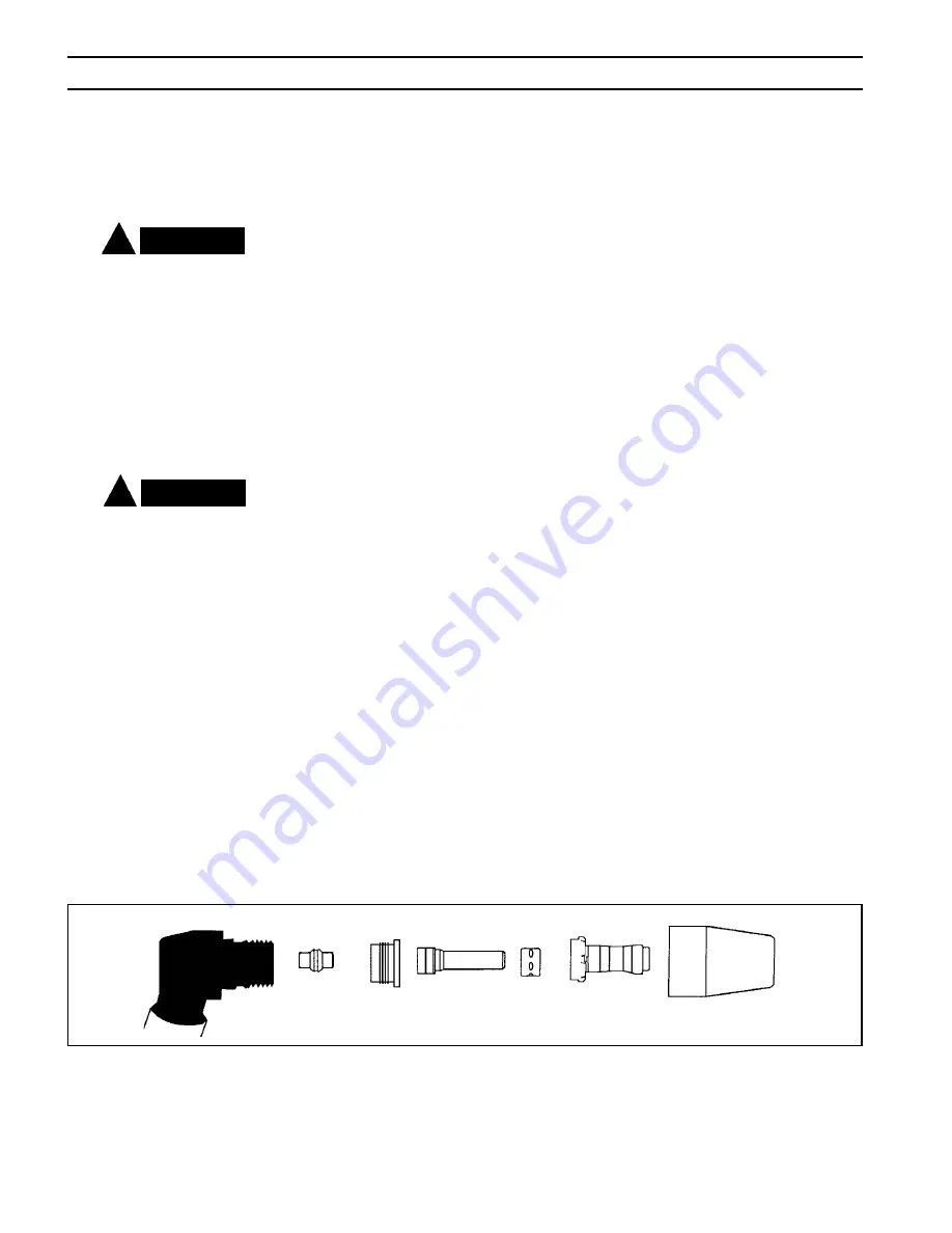
2.7 PT-31xl TORCh CONSUmABleS INSTAllATION
Figure 2-6 Assembly of “xT” Consumable Parts
NOTE: Nozzles
Marked By
Amperage
0558006190
Plunger
Seat
0558006191
Electrode
0558006192
0558006189
Baffle
Nozzle
Heat Shield
0558006185
30/40A
0558006187
1. To disassemble the front end, hold the torch with the shield in an upright position.
This will prevent the nozzle, electrode, and swirl baffle from falling free when the
shield is removed.
The gas flow check valve is part of the safety interlock and is permanently as-
sembled in the torch head. The head must be replaced if this valve malfunctions.
The light spring force used to close the ball check can be felt by pushing on the
electrode when assembling the front end components.
2. Periodically check the heat shield, electrode, nozzle, and swirl baffle. Replace if
worn or damaged.
3. Do not continue to use if the electrode end erodes to a length shorter than 16mm
[5/8 in.] as shown in Fugure 2-6 below.
4. Apply a small amount of lubricant P/N 0558000443 (17672), supplied in spare parts
kit, to the heat shield or to the o-ring as shown in Figure 4-3. Check o-ring for
damage whenever the shield is removed. Replace if necessary.
Содержание 380
Страница 4: ... TABLE OF CONTENTS ...
Страница 14: ...14 SECTION 1 DESCRIPTION ...
Страница 26: ...26 SECTION 3 OPERATION ...
Страница 30: ...30 SECTION 4 MAINTENANCE WORK LEAD CONNECTION TORCH CONNECTION ...
Страница 41: ...41 Notes ...
Страница 42: ...Notes ...
Страница 43: ...Revision History Original release 06 2006 03 2007 Revised Title Page layout text ...


