background image

Page 15

Series 500 Installation Guide

The PS510 has a simple control system for controlling a display device (LCD, Plasma, or Projec-
tor). The serial port is connected directly to the display device. Codes are uploaded and stored 
in the Series 500. When the system is inac  ve and an input source is selected the projector 
is sent a “power on” command. When the signal is lost and a predetermined amount of   me 
passes, the Series 500 issues a “power down” command.

Main Form

Main Form

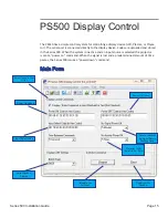
PS500 Display Control

Power On Codes

Power Off Codes

Input Select Code

Serial Speed of 

Display

Time to Wait with 
No Signal Before 

Shutting Down

Projector / LCD 

Bulb Life Fail Safe

Upload to  the 

Switcher

Read from the 

Switcher

Enter Codes in Text 

or HEX

Содержание PS510

Страница 1: ...Presentation Switchers Series 500 Installation Guide PS510 Under Table Presentation Switcher October 2012 PN DOC 000005 00A...

Страница 2: ...dback Customer Feedback We are constantly working to improve the quality of our documenta on and we would appreciate your feedback Please send email to marke ng Presenta onSwitchers com 2012 Presenta...

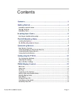
Страница 3: ...g Devices 9 Input Devices Sources 9 Connecting Display or Video Output Devices 9 Connecting Audio Output Devices 10 Connecting Control Devices 11 Configuring the PS510 12 The Configuration Software 12...

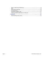
Страница 4: ...Inc Relay Contact Closure Enable Flag 19 Mode 19 Testing the Display Codes 20 Testing the Relays 20 Testing the Complete System 21 Enabling or Disabling the Display Control Feature 21 Appendix 22 Ser...

Страница 5: ...and output devices to the switcher 6 Power up the unit and test the unit manually 7 Make adjustments to the system as necessary 8 Test the system again using external control devices as necessary Pack...

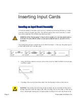
Страница 6: ...m the PS510 enclosure to prevent accidental shock to yourself or to the equipment The drawing below shows a sample layout of a PS510 enclosure In this case the system type is a PS510 with HDMI DVI and...

Страница 7: ...ctronic component 3 Remove the input board assembly from the protec ve conduc ve packaging 4 Insert the new input board assembly into the enclosure while aligning card within the guides on the le and...

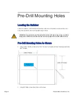
Страница 8: ...eople s legs or knees WARNING Keep product away from poten al contact with human legs knees and other body parts A PS510 is made of metal and can harm people if struck with su cient force Pre Drill Mo...

Страница 9: ...tor This device is now considered Input 2 Note The LED located just above the stereo connector will illuminate red when power is present on the card The LED will illuminate green when an ac ve video s...

Страница 10: ...device This includes audio from analog sources that are digi zed and embedded onto the HDMI stream HDCP Encrypted Sources HDCP Encrypted Sources Signals which are encrypted using HDCP will pass direct...

Страница 11: ...sted using the Configura on U lity discussed in more detail later in this guide The default baud rate for the serial port is 115200 Display Control Display Control The PS510 has a simple control syste...

Страница 12: ...Inc Configuring the PS510 The Configuration Software The Configuration Software The PS510 Configura on So ware is available on the website on the PS510 produce web page This applica on requires a conn...

Страница 13: ...ng the audio back up The Audio Input Levels feature of the PS510 would allow you to set the audio level of the cable receiver box slightly lower such that all source devices have the same nominal leve...

Страница 14: ...when a control panel is used and when current configura on status is maintained Without the unsolicited feedback the programmer would have to constantly ask the PS510 if anything has changed o en cal...

Страница 15: ...inac ve and an input source is selected the projector is sent a power on command When the signal is lost and a predetermined amount of me passes the Series 500 issues a power down command Main Form M...

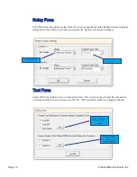
Страница 16: ...S500 7 slot rack mount systems Ignore references to Relays Test Form Test Form Select the Test pull down menu to access this form This rou ne is used to test the commands you have entered Be sure to s...

Страница 17: ...down menu set the baud rate to the speed of the switcher The switcher defaults to 115 200 baud Entering Display Codes Entering Display Codes Hexidecimal or Text Hexidecimal or Text Display codes can...

Страница 18: ...before it powers down the display This delay is created for mes when an input is errantly selected or when transi oning between sources Time Between Commands Time Between Commands Some projectors nee...

Страница 19: ...Turn On first then press the Test bu on The display device should turn on If it does not verify the codes are correct cabling is correct and communica ons parameters are correct and repeat the test R...

Страница 20: ...Page 20 Presentation Switchers Inc Appendix Series 500 Programming Codes 21 22...

Страница 21: ...nput selected by the switcher Examples Send Response SO1T 3 Requested status on output number 1 reveals 3 as the current selected input SO1T 5 Requested status on output number 1 reveals input 5 Volum...

Страница 22: ...e before mute Examples Send Response VUT None Volume level returns to audio level prior to mute Mute Video ZM T Mute video output Image shows disconnected Examples Send Response ZMT None Turns Video O...

Страница 23: ...s 500 Installation Guide Presentation Switchers 15364 E Valley Blvd City of Industry CA 91746 United States of America www Presenta onSwitchers com US CAN Toll Free 800 614 9958 Voice 909 829 5724 Fax...

Отзывы: