Page 7
Series 500 Installation Guide
The following precau ons must be taken.
a.
Do not open the protec ve conduc ve packaging un l you have read the following, and
are at an approved an -sta c work sta on.
b.
Always discharge yourself by touching a grounded bare metal surface before picking up
an ESD - sensi ve electronic component.
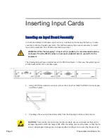
3. Remove the input board assembly from the protec ve conduc ve packaging.
4. Insert the new input board assembly into the enclosure while aligning card within the
guides on the le and right of the opening. Press the card
fi
rmly (about 10 lbs of force) into
the card slot.
5. Using the screw extracted from the IN500 Future Expansion plate, fasten the new input
board assembly in place.
6. Connect power cord to enclosure and turn system on.
7. The system is now ready for use and the new input is ac ve.


